正在加载图片...
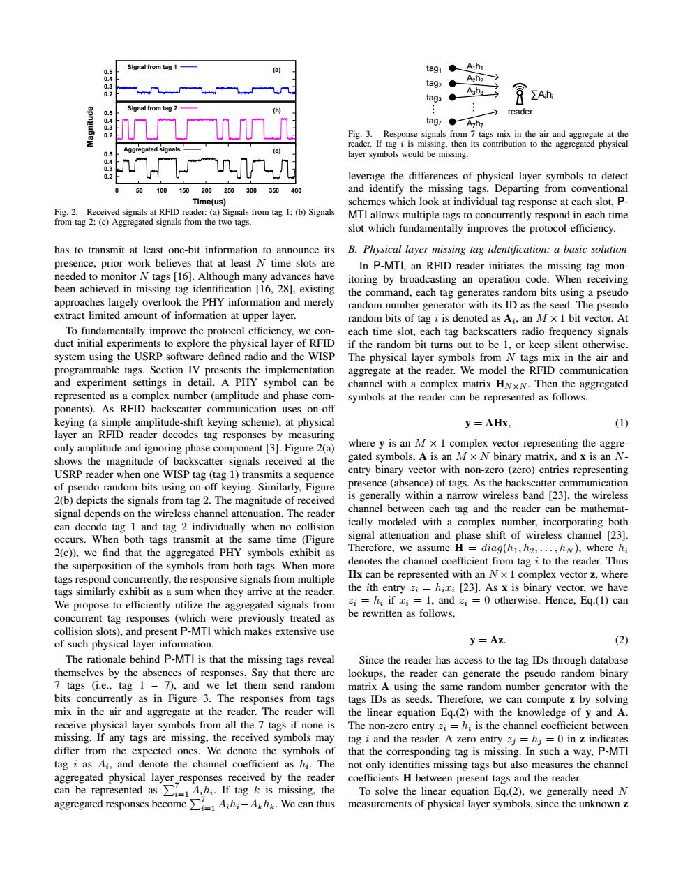
Signal from tag 1 (a) tag1 ●Ah tag2 ● A2h2 0.2 tag3 A3ha ∑Ah Signal from tao 2 05 (b) reader tag7●Azh Fig.3.Response signals from 7 tags mix in the air and aggregate at the Aggregated signals reader.If tag i is missing,then its contribution to the aggregated physical 05 layer symbols would be missing 4 0.2 leverage the differences of physical layer symbols to detect 50 100 150 200 250 300 350 40 and identify the missing tags.Departing from conventional Time(us) schemes which look at individual tag response at each slot,P- Fig.2.Received signals at RFID reader:(a)Signals from tag 1:(b)Signals from tag 2;(c)Aggregated signals from the two tags. MTI allows multiple tags to concurrently respond in each time slot which fundamentally improves the protocol efficiency. has to transmit at least one-bit information to announce its B.Physical layer missing tag identification:a basic solution presence,prior work believes that at least N time slots are In P-MTI,an RFID reader initiates the missing tag mon- needed to monitor N tags [16].Although many advances have itoring by broadcasting an operation code.When receiving been achieved in missing tag identification [16,28],existing the command,each tag generates random bits using a pseudo approaches largely overlook the PHY information and merely random number generator with its ID as the seed.The pseudo extract limited amount of information at upper layer. random bits of tag i is denoted as A;,an M x 1 bit vector.At To fundamentally improve the protocol efficiency,we con- each time slot,each tag backscatters radio frequency signals duct initial experiments to explore the physical layer of RFID if the random bit turns out to be 1,or keep silent otherwise. system using the USRP software defined radio and the WISP The physical layer symbols from N tags mix in the air and programmable tags.Section IV presents the implementation aggregate at the reader.We model the RFID communication and experiment settings in detail.A PHY symbol can be channel with a complex matrix HNxN.Then the aggregated represented as a complex number(amplitude and phase com- symbols at the reader can be represented as follows. ponents).As RFID backscatter communication uses on-off keying(a simple amplitude-shift keying scheme),at physical y=AHx. (1) layer an RFID reader decodes tag responses by measuring only amplitude and ignoring phase component [3].Figure 2(a) where y is an M x 1 complex vector representing the aggre- shows the magnitude of backscatter signals received at the gated symbols,A is an Mx N binary matrix,and x is an N- USRP reader when one WISP tag (tag 1)transmits a sequence entry binary vector with non-zero (zero)entries representing of pseudo random bits using on-off keying.Similarly,Figure presence (absence)of tags.As the backscatter communication 2(b)depicts the signals from tag 2.The magnitude of received is generally within a narrow wireless band [23],the wireless signal depends on the wireless channel attenuation.The reader channel between each tag and the reader can be mathemat- can decode tag 1 and tag 2 individually when no collision ically modeled with a complex number,incorporating both occurs.When both tags transmit at the same time (Figure signal attenuation and phase shift of wireless channel [23]. 2(c)),we find that the aggregated PHY symbols exhibit as Therefore,we assume H =diag(h1,h2,...,hN),where hi the superposition of the symbols from both tags.When more denotes the channel coefficient from tag i to the reader.Thus tags respond concurrently,the responsive signals from multiple Hx can be represented with an Nx 1 complex vector z,where tags similarly exhibit as a sum when they arrive at the reader. the ith entry zi=hixi [23].As x is binary vector,we have We propose to efficiently utilize the aggregated signals from zi=hi if xi=1,andzi=0 otherwise.Hence,Eg.(1)can concurrent tag responses (which were previously treated as be rewritten as follows, collision slots),and present P-MTI which makes extensive use of such physical layer information. y=Az. (2) The rationale behind P-MTI is that the missing tags reveal Since the reader has access to the tag IDs through database themselves by the absences of responses.Say that there are lookups,the reader can generate the pseudo random binary 7 tags (ie.,tag 1-7),and we let them send random matrix A using the same random number generator with the bits concurrently as in Figure 3.The responses from tags tags IDs as seeds.Therefore,we can compute z by solving mix in the air and aggregate at the reader.The reader will the linear equation Eg.(2)with the knowledge of y and A. receive physical layer symbols from all the 7 tags if none is The non-zero entry zi=hi is the channel coefficient between missing.If any tags are missing,the received symbols may tag i and the reader.A zero entry zj=hj=0 in z indicates differ from the expected ones.We denote the symbols of that the corresponding tag is missing.In such a way,P-MTI tag i as Ai,and denote the channel coefficient as hi.The not only identifies missing tags but also measures the channel aggregated physical layer responses received by the reader 7 coefficients H between present tags and the reader. can be represented asAhi.If tag k is missing.the To solve the linear equation Eq.(2),we generally need N aggregated responses becomeAhA We can thus measurements of physical layer symbols,since the unknown z0.2 0.3 0.4 0.5 Signal from tag 1 0.2 0.3 0.4 0.5 Signal from tag 2 0.2 0.3 0.4 0.5 0 50 100 150 200 250 300 350 400 (a) (b) (c) Time(us) Magnitude Aggregated signals Fig. 2. Received signals at RFID reader: (a) Signals from tag 1; (b) Signals from tag 2; (c) Aggregated signals from the two tags. has to transmit at least one-bit information to announce its presence, prior work believes that at least N time slots are needed to monitor N tags [16]. Although many advances have been achieved in missing tag identification [16, 28], existing approaches largely overlook the PHY information and merely extract limited amount of information at upper layer. To fundamentally improve the protocol efficiency, we conduct initial experiments to explore the physical layer of RFID system using the USRP software defined radio and the WISP programmable tags. Section IV presents the implementation and experiment settings in detail. A PHY symbol can be represented as a complex number (amplitude and phase components). As RFID backscatter communication uses on-off keying (a simple amplitude-shift keying scheme), at physical layer an RFID reader decodes tag responses by measuring only amplitude and ignoring phase component [3]. Figure 2(a) shows the magnitude of backscatter signals received at the USRP reader when one WISP tag (tag 1) transmits a sequence of pseudo random bits using on-off keying. Similarly, Figure 2(b) depicts the signals from tag 2. The magnitude of received signal depends on the wireless channel attenuation. The reader can decode tag 1 and tag 2 individually when no collision occurs. When both tags transmit at the same time (Figure 2(c)), we find that the aggregated PHY symbols exhibit as the superposition of the symbols from both tags. When more tags respond concurrently, the responsive signals from multiple tags similarly exhibit as a sum when they arrive at the reader. We propose to efficiently utilize the aggregated signals from concurrent tag responses (which were previously treated as collision slots), and present P-MTI which makes extensive use of such physical layer information. The rationale behind P-MTI is that the missing tags reveal themselves by the absences of responses. Say that there are 7 tags (i.e., tag 1 – 7), and we let them send random bits concurrently as in Figure 3. The responses from tags mix in the air and aggregate at the reader. The reader will receive physical layer symbols from all the 7 tags if none is missing. If any tags are missing, the received symbols may differ from the expected ones. We denote the symbols of tag i as Ai , and denote the channel coefficient as hi . The aggregated physical layer responses received by the reader can be represented as P7 i=1 Aihi . If tag k is missing, the aggregated responses become P7 i=1 Aihi−Akhk. We can thus FNEB O(n) 1 2 3 4 5 6 7 8 9 10 11 ZOE id1 id2 idn ... id3 id4 OR P P P P P P ZOE id1 id2 idn OR P P P P id3 P id4 ... P node4 A1h1 node1 node2 node3 A3h3 A A4h4 2h2 A1h1 node1 node2 A2h2 A4h4 node4 node3 A3h3 ∑Aihi node A1h1 1 node2 A2h2 A4h4 node4 node3 A3h3 ∑Aihi station node A1h1 1 node2 A2h2 A7h7 node7 node3 A3h3 ∑Aihi station ... ... tag A1h1 1 tag2 A2h2 A7h7 tag7 tag3 A3h3 ∑Aihi reader ... ... Fig. 3. Response signals from 7 tags mix in the air and aggregate at the reader. If tag i is missing, then its contribution to the aggregated physical layer symbols would be missing. leverage the differences of physical layer symbols to detect and identify the missing tags. Departing from conventional schemes which look at individual tag response at each slot, PMTI allows multiple tags to concurrently respond in each time slot which fundamentally improves the protocol efficiency. B. Physical layer missing tag identification: a basic solution In P-MTI, an RFID reader initiates the missing tag monitoring by broadcasting an operation code. When receiving the command, each tag generates random bits using a pseudo random number generator with its ID as the seed. The pseudo random bits of tag i is denoted as Ai , an M ×1 bit vector. At each time slot, each tag backscatters radio frequency signals if the random bit turns out to be 1, or keep silent otherwise. The physical layer symbols from N tags mix in the air and aggregate at the reader. We model the RFID communication channel with a complex matrix HN×N . Then the aggregated symbols at the reader can be represented as follows. y = AHx, (1) where y is an M × 1 complex vector representing the aggregated symbols, A is an M × N binary matrix, and x is an Nentry binary vector with non-zero (zero) entries representing presence (absence) of tags. As the backscatter communication is generally within a narrow wireless band [23], the wireless channel between each tag and the reader can be mathematically modeled with a complex number, incorporating both signal attenuation and phase shift of wireless channel [23]. Therefore, we assume H = diag(h1, h2, . . . , hN ), where hi denotes the channel coefficient from tag i to the reader. Thus Hx can be represented with an N ×1 complex vector z, where the ith entry zi = hixi [23]. As x is binary vector, we have zi = hi if xi = 1, and zi = 0 otherwise. Hence, Eq.(1) can be rewritten as follows, y = Az. (2) Since the reader has access to the tag IDs through database lookups, the reader can generate the pseudo random binary matrix A using the same random number generator with the tags IDs as seeds. Therefore, we can compute z by solving the linear equation Eq.(2) with the knowledge of y and A. The non-zero entry zi = hi is the channel coefficient between tag i and the reader. A zero entry zj = hj = 0 in z indicates that the corresponding tag is missing. In such a way, P-MTI not only identifies missing tags but also measures the channel coefficients H between present tags and the reader. To solve the linear equation Eq.(2), we generally need N measurements of physical layer symbols, since the unknown z