正在加载图片...
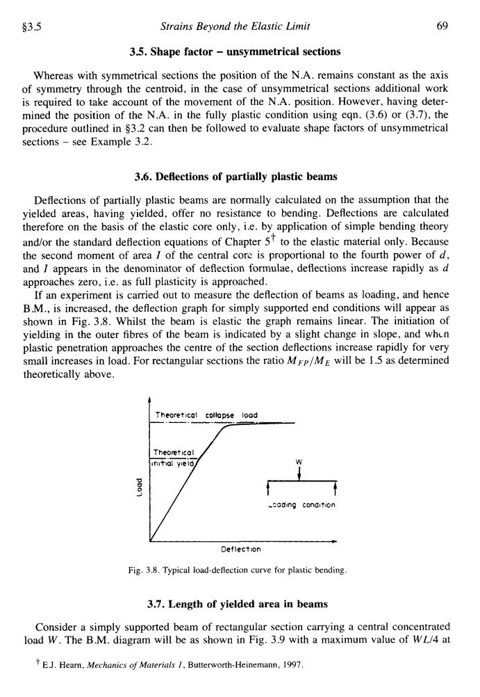
$3.5 Strains Beyond the Elastic Limit 69 3.5.Shape factor-unsymmetrical sections Whereas with symmetrical sections the position of the N.A.remains constant as the axis of symmetry through the centroid,in the case of unsymmetrical sections additional work is required to take account of the movement of the N.A.position.However,having deter- mined the position of the N.A.in the fully plastic condition using eqn.(3.6)or(3.7),the procedure outlined in $3.2 can then be followed to evaluate shape factors of unsymmetrical sections-see Example 3.2. 3.6.Deflections of partially plastic beams Deflections of partially plastic beams are normally calculated on the assumption that the yielded areas,having yielded,offer no resistance to bending.Deflections are calculated therefore on the basis of the elastic core only,i.e.by application of simple bending theory and/or the standard deflection equations of Chapter 5f to the elastic material only.Because the second moment of area I of the central core is proportional to the fourth power of d, and I appears in the denominator of deflection formulae,deflections increase rapidly as d approaches zero,i.e.as full plasticity is approached. If an experiment is carried out to measure the deflection of beams as loading,and hence B.M.,is increased,the deflection graph for simply supported end conditions will appear as shown in Fig.3.8.Whilst the beam is elastic the graph remains linear.The initiation of yielding in the outer fibres of the beam is indicated by a slight change in slope,and when plastic penetration approaches the centre of the section deflections increase rapidly for very small increases in load.For rectangular sections the ratio MFP/ME will be 1.5 as determined theoretically above. Theoretical collapse lood Theoretical initial yield/ _ading condition Deflection Fig.3.8.Typical load-deflection curve for plastic bending. 3.7.Length of yielded area in beams Consider a simply supported beam of rectangular section carrying a central concentrated load W.The B.M.diagram will be as shown in Fig.3.9 with a maximum value of WL/4 at EJ.Hearn,Mechanics of Materials 1.Butterworth-Heinemann,1997.$3.5 Strains Beyond the Elastic Limit 69 35. Shape factor - unsymmetrical sections Whereas with symmetrical sections the position of the N.A. remains constant as the axis of symmetry through the centroid, in the case of unsymmetrical sections additional work is required to take account of the movement of the N.A. position. However, having determined the position of the N.A. in the fully plastic condition using eqn. (3.6) or (3.7), the procedure outlined in $3.2 can then be followed to evaluate shape factors of unsymmetrical sections - see Example 3.2. 3.6. Deflections of partially plastic beams Deflections of partially plastic beams are normally calculated on the assumption that the yielded areas, having yielded, offer no resistance to bending. Deflections are calculated therefore on the basis of the elastic core only, i.e. by application of simple bending theory t and/or the standard deflection equations of Chapter 5 to the elastic material only. Because the second moment of area I of the central cors is proportional to the fourth power of d, and I appears in the denominator of deflection formulae, deflections increase rapidly as d approaches zero, i.e. as full plasticity is approached. If an experiment is carried out to measure the deflection of beams as loading, and hence B.M., is increased, the deflection graph for simply supported end conditions will appear as shown in Fig. 3.8. Whilst the beam is elastic the graph remains linear. The initiation of yielding in the outer fibres of the beam is indicated by a slight change in slope, and whtn plastic penetration approaches the centre of the section deflections increase rapidly for very small increases in load. For rectangular sections the ratio MFP/ME will be 1.5 as determined theoretically above. P J x Theoretical collapse load Theoret lcal w -2oding condition L Deflection / Fig. 3.8. Typical load-deflection curve for plastic bending 3.7. Length of yielded area in beams Consider a simply supported beam of rectangular section carrying a central concentrated load W. The B.M. diagram will be as shown in Fig. 3.9 with a maximum value of WL/4 at E.J. Hearn, Mechanics of Materials I, Butterworth-Heinemann, 1997