正在加载图片...

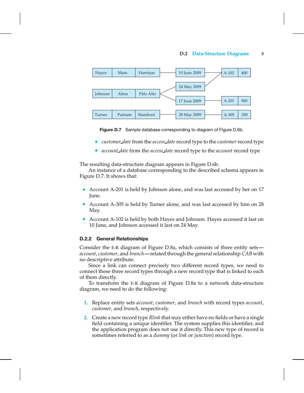
D.2 Data-Structure Diagrams 5 Hayes Main Harrison 10 June 2009 A-102 400 24May2009 Johnson Alma Palo Alto 17June2009 A-201 900 Turner Putnam Stamford 28May2009 A-305 350 Figure D.7 Sample database corresponding to diagram of Figure D.6b. customer date from the access date record type to the customer record type .account date from the access date record type to the account record type The resulting data-structure diagram appears in Figure D.6b. An instance of a database corresponding to the described schema appears in Figure D.7.It shows that: Account A-201 is held by Johnson alone,and was last accessed by her on 17 June Account A-305 is held by Turner alone,and was last accessed by him on 28 May. Account A-102 is held by both Hayes and Johnson.Hayes accessed it last on 10 June,and Johnson accessed it last on 24 May. D.2.2 General Relationships Consider the E-R diagram of Figure D.8a,which consists of three entity sets- account,customer,and branch-related through the general relationship CAB with no descriptive attribute. Since a link can connect precisely two different record types,we need to connect these three record types through a new record type that is linked to each of them directly. To transform the E-R diagram of Figure D.8a to a network data-structure diagram,we need to do the following: 1.Replace entity sets account,customer,and branch with record types account, customer,and branch,respectively. 2.Create a new record type Rlink that may either have no fields or have a single field containing a unique identifier.The system supplies this identifier,and the application program does not use it directly.This new type of record is sometimes referred to as a dummy(or link or junction)record type.D.2 Data-Structure Diagrams 5 Figure D.7 Sample database corresponding to diagram of Figure D.6b. • customer date from the access date record type to the customer record type • account date from the access date record type to the account record type The resulting data-structure diagram appears in Figure D.6b. An instance of a database corresponding to the described schema appears in Figure D.7. It shows that: • Account A-201 is held by Johnson alone, and was last accessed by her on 17 June. • Account A-305 is held by Turner alone, and was last accessed by him on 28 May. • Account A-102 is held by both Hayes and Johnson. Hayes accessed it last on 10 June, and Johnson accessed it last on 24 May. D.2.2 General Relationships Consider the E-R diagram of Figure D.8a, which consists of three entity sets— account, customer, and branch—related through the general relationship CAB with no descriptive attribute. Since a link can connect precisely two different record types, we need to connect these three record types through a new record type that is linked to each of them directly. To transform the E-R diagram of Figure D.8a to a network data-structure diagram, we need to do the following: 1. Replace entity sets account, customer, and branch with record types account, customer, and branch, respectively. 2. Create a new record type Rlink that may either have no fields or have a single field containing a unique identifier. The system supplies this identifier, and the application program does not use it directly. This new type of record is sometimes referred to as a dummy (or link or junction) record type