正在加载图片...

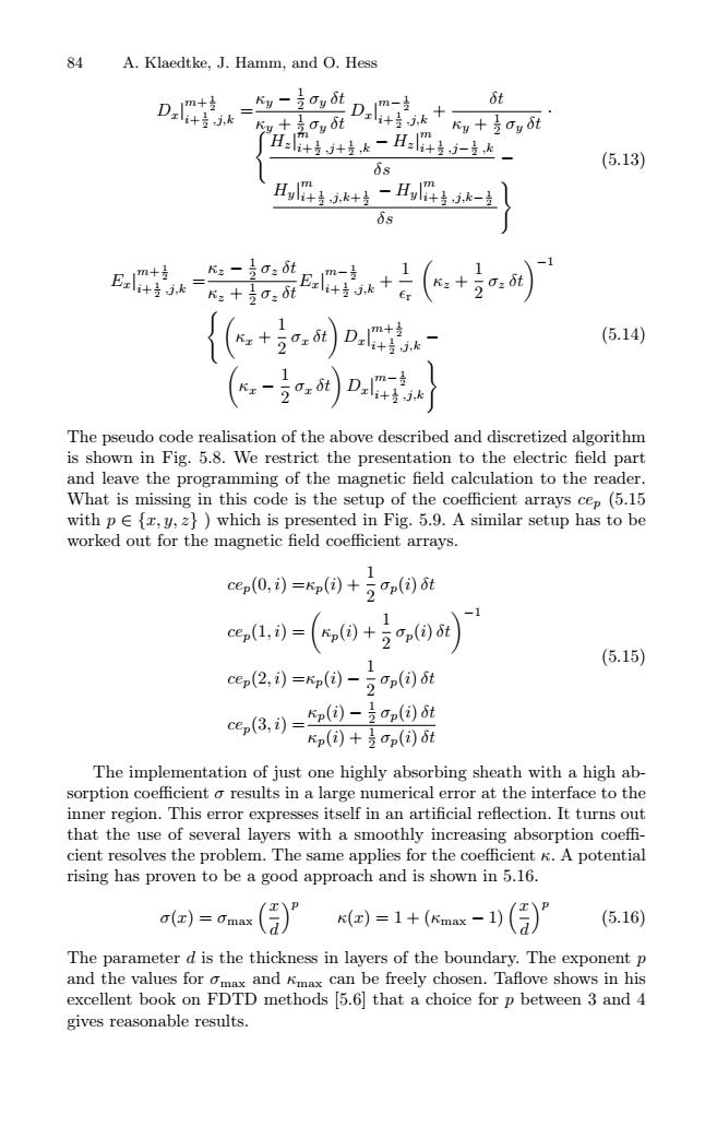
84 A.Klaedtke,J.Hamm,and O.Hess D.4=- D.+ St Ky +Oy ot ku+3oy8t H+-H:4-达 6s (5.13) H,4.k+专-H,件生k-生 δs (5.14) The pseudo code realisation of the above described and discretized algorithm is shown in Fig.5.8.We restrict the presentation to the electric field part and leave the programming of the magnetic field calculation to the reader. What is missing in this code is the setup of the coefficient arrays cep(5.15 with p{,y,z})which is presented in Fig.5.9.A similar setup has to be worked out for the magnetic field coefficient arrays. 1 ce,(0,)=n(间+2mn(间6t e,1,)-(,间+间i) 1 (5.15) cep(2,)=Kn(-2n(间t ce,3,)=(园-支)t p()+是on()t The implementation of just one highly absorbing sheath with a high ab- sorption coefficient o results in a large numerical error at the interface to the inner region.This error expresses itself in an artificial reflection.It turns out that the use of several layers with a smoothly increasing absorption coeffi- cient resolves the problem.The same applies for the coefficient K.A potential rising has proven to be a good approach and is shown in 5.16 a()=dmax )=1+(x-(月) (5.16) The parameter d is the thickness in layers of the boundary.The exponent p and the values for omax and Kmax can be freely chosen.Taflove shows in his excellent book on FDTD methods [5.6 that a choice for p between 3 and 4 gives reasonable results.84 A. Klaedtke, J. Hamm, and O. Hess Dx| m+ 1 2 i+ 1 2 ,j,k =κy − 1 2 σy δt κy + 1 2 σy δt Dx| m− 1 2 i+ 1 2 ,j,k + δt κy + 1 2 σy δt · Hz| m i+ 1 2 ,j+ 1 2 ,k − Hz| m i+ 1 2 ,j− 1 2 ,k δs − Hy| m i+ 1 2 ,j,k+ 1 2 − Hy| m i+ 1 2 ,j,k− 1 2 δs , (5.13) Ex| m+ 1 2 i+ 1 2 ,j,k =κz − 1 2 σz δt κz + 1 2 σz δt Ex| m− 1 2 i+ 1 2 ,j,k + 1 r κz + 1 2 σz δt−1 κx + 1 2 σx δt Dx| m+ 1 2 i+ 1 2 ,j,k − κx − 1 2 σx δt Dx| m− 1 2 i+ 1 2 ,j,k, (5.14) The pseudo code realisation of the above described and discretized algorithm is shown in Fig. 5.8. We restrict the presentation to the electric field part and leave the programming of the magnetic field calculation to the reader. What is missing in this code is the setup of the coefficient arrays cep (5.15 with p ∈ {x, y, z} ) which is presented in Fig. 5.9. A similar setup has to be worked out for the magnetic field coefficient arrays. cep(0, i) =κp(i) + 1 2 σp(i) δt cep(1, i) = κp(i) + 1 2 σp(i) δt−1 cep(2, i) =κp(i) − 1 2 σp(i) δt cep(3, i) =κp(i) − 1 2 σp(i) δt κp(i) + 1 2 σp(i) δt (5.15) The implementation of just one highly absorbing sheath with a high absorption coefficient σ results in a large numerical error at the interface to the inner region. This error expresses itself in an artificial reflection. It turns out that the use of several layers with a smoothly increasing absorption coeffi- cient resolves the problem. The same applies for the coefficient κ. A potential rising has proven to be a good approach and is shown in 5.16. σ(x) = σmax x d p κ(x)=1+(κmax − 1) x d p (5.16) The parameter d is the thickness in layers of the boundary. The exponent p and the values for σmax and κmax can be freely chosen. Taflove shows in his excellent book on FDTD methods [5.6] that a choice for p between 3 and 4 gives reasonable results