正在加载图片...
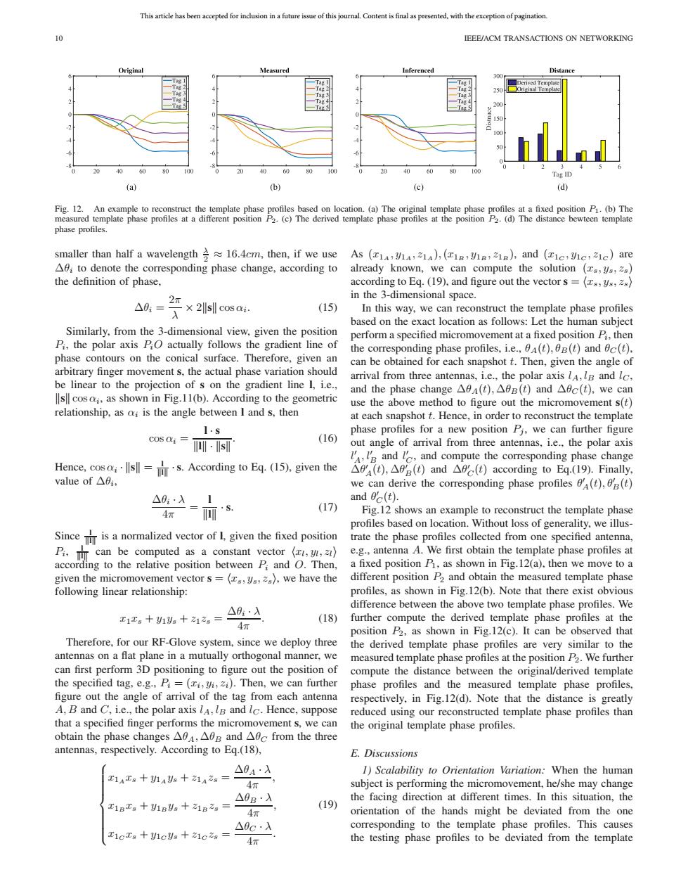
This article has been accepted for inclusion in a future issue of this journal.Content is final as presented,with the exception of pagination 10 IEEE/ACM TRANSACTIONS ON NETWORKING Original Measured Inferenced Distance Derived Template 150 1 0 Tag ID (a) (b) (c) (d) Fig.12.An example to reconstruct the template phase profiles based on location.(a)The original template phase profiles at a fixed position P1.(b)The measured template phase profiles at a different position P2.(c)The derived template phase profiles at the position P2.(d)The distance bewteen template phase profiles. smaller than half a wavelength 16.4cm,then,if we use As (1a:VA,21),(18:V8:218),and (ic:Vc,z1c)are A0i to denote the corresponding phase change,according to already known,we can compute the solution (s,ys,2s) the definition of phase. according to Eq.(19),and figure out the vector s =(s,ys,2s) 2π in the 3-dimensional space. △9,=入×2 cos i. (15) In this way,we can reconstruct the template phase profiles based on the exact location as follows:Let the human subject Similarly,from the 3-dimensional view,given the position perform a specified micromovement at a fixed position Pi.then P,the polar axis PO actually follows the gradient line of the corresponding phase profiles,i.e.,(t),0B(t)and ec(t). phase contours on the conical surface.Therefore,given an can be obtained for each snapshot t.Then,given the angle of arbitrary finger movement s,the actual phase variation should be linear to the projection of s on the gradient line 1,i.e., arrival from three antennas,i.e.,the polar axis lA,IB and lc, and the phase change△0a(t),△0B(t)and△fc(t),we can s cosai,as shown in Fig.11(b).According to the geometric use the above method to figure out the micromovement s(t) relationship,as a;is the angle between I and s,then at each snapshot t.Hence,in order to reconstruct the template 1.s phase profiles for a new position Pi,we can further figure Cos ai= (16 ·s out angle of arrival from three antennas,i.e..the polar axis I and I,and compute the corresponding phase change Hence,cos;s.According to Eq.(15).given the △fa(t),△fe(t)and△c(t)according to Eq.(19).Finally,. value of△0. we can derive the corresponding phase profiles (t),(t) △8·入1 and 0c(t). (17) Fig.12 shows an example to reconstruct the template phase profiles based on location.Without loss of generality,we illus- Sinceis a normalized vector of 1,given the fixed position trate the phase profiles collected from one specified antenna, P.can be computed as a constant vector (,z) e.g.,antenna A.We first obtain the template phase profiles at according to the relative position between Pi and O.Then, a fixed position P,as shown in Fig.12(a),then we move to a given the micromovement vector s=(s,ys,2),we have the different position P2 and obtain the measured template phase following linear relationship: profiles,as shown in Fig.12(b).Note that there exist obvious △0·入 difference between the above two template phase profiles.We 工1工g+1别g十a1之。= (18) further compute the derived template phase profiles at the 4π position P2,as shown in Fig.12(c).It can be observed that Therefore,for our RF-Glove system,since we deploy three the derived template phase profiles are very similar to the antennas on a flat plane in a mutually orthogonal manner,we measured template phase profiles at the position P2.We further can first perform 3D positioning to figure out the position of compute the distance between the original/derived template the specified tag,e.g.,Pi=(zi,yi,zi).Then,we can further phase profiles and the measured template phase profiles, figure out the angle of arrival of the tag from each antenna respectively,in Fig.12(d).Note that the distance is greatly A,B and C.i.e.,the polar axis lA,IB and lc.Hence,suppose reduced using our reconstructed template phase profiles than that a specified finger performs the micromovement s,we can the original template phase profiles. obtain the phase changes△fA,△0B and△9 c from the three antennas,respectively.According to Eq.(18), E.Discussions △0A·入 1)Scalability to Orientation Variation:When the human 工1A工8十1As十21A2g= subject is performing the micromovement,he/she may change △0B·入 the facing direction at different times.In this situation,the E1Bx8+1Bs十1B2g= (19) 4 orientation of the hands might be deviated from the one △0c·入 corresponding to the template phase profiles.This causes 工1cD8+1cs+21c28= 4π the testing phase profiles to be deviated from the templateThis article has been accepted for inclusion in a future issue of this journal. Content is final as presented, with the exception of pagination. 10 IEEE/ACM TRANSACTIONS ON NETWORKING Fig. 12. An example to reconstruct the template phase profiles based on location. (a) The original template phase profiles at a fixed position P1. (b) The measured template phase profiles at a different position P2. (c) The derived template phase profiles at the position P2. (d) The distance bewteen template phase profiles. smaller than half a wavelength λ 2 ≈ 16.4cm, then, if we use Δθi to denote the corresponding phase change, according to the definition of phase, Δθi = 2π λ × 2s cos αi. (15) Similarly, from the 3-dimensional view, given the position Pi, the polar axis PiO actually follows the gradient line of phase contours on the conical surface. Therefore, given an arbitrary finger movement s, the actual phase variation should be linear to the projection of s on the gradient line l, i.e., s cosαi, as shown in Fig.11(b). According to the geometric relationship, as αi is the angle between l and s, then cos αi = l · s l·s . (16) Hence, cos αi · s = l l ·s. According to Eq. (15), given the value of Δθi, Δθi · λ 4π = l l · s. (17) Since l l is a normalized vector of l, given the fixed position Pi, l l can be computed as a constant vector
xl, yl, zl
according to the relative position between Pi and O. Then, given the micromovement vector s =
xs, ys, zs
, we have the following linear relationship: x1xs + y1ys + z1zs = Δθi · λ 4π . (18) Therefore, for our RF-Glove system, since we deploy three antennas on a flat plane in a mutually orthogonal manner, we can first perform 3D positioning to figure out the position of the specified tag, e.g., Pi = (xi, yi, zi). Then, we can further figure out the angle of arrival of the tag from each antenna A, B and C, i.e., the polar axis lA, lB and lC . Hence, suppose that a specified finger performs the micromovement s, we can obtain the phase changes ΔθA, ΔθB and ΔθC from the three antennas, respectively. According to Eq.(18), ⎧ ⎪⎪⎪⎪⎪⎪⎨ ⎪⎪⎪⎪⎪⎪⎩ x1A xs + y1A ys + z1A zs = ΔθA · λ 4π , x1B xs + y1B ys + z1B zs = ΔθB · λ 4π , x1C xs + y1C ys + z1C zs = ΔθC · λ 4π . (19) As (x1A , y1A , z1A ),(x1B , y1B , z1B ), and (x1C , y1C , z1C ) are already known, we can compute the solution (xs, ys, zs) according to Eq. (19), and figure out the vector s =
xs, ys, zs
in the 3-dimensional space. In this way, we can reconstruct the template phase profiles based on the exact location as follows: Let the human subject perform a specified micromovement at a fixed position Pi, then the corresponding phase profiles, i.e., θA(t), θB(t) and θC (t), can be obtained for each snapshot t. Then, given the angle of arrival from three antennas, i.e., the polar axis lA, lB and lC, and the phase change ΔθA(t), ΔθB(t) and ΔθC (t), we can use the above method to figure out the micromovement s(t) at each snapshot t. Hence, in order to reconstruct the template phase profiles for a new position Pj , we can further figure out angle of arrival from three antennas, i.e., the polar axis l A, l B and l C , and compute the corresponding phase change Δθ A(t), Δθ B(t) and Δθ C (t) according to Eq.(19). Finally, we can derive the corresponding phase profiles θ A(t), θ B(t) and θ C (t). Fig.12 shows an example to reconstruct the template phase profiles based on location. Without loss of generality, we illustrate the phase profiles collected from one specified antenna, e.g., antenna A. We first obtain the template phase profiles at a fixed position P1, as shown in Fig.12(a), then we move to a different position P2 and obtain the measured template phase profiles, as shown in Fig.12(b). Note that there exist obvious difference between the above two template phase profiles. We further compute the derived template phase profiles at the position P2, as shown in Fig.12(c). It can be observed that the derived template phase profiles are very similar to the measured template phase profiles at the position P2. We further compute the distance between the original/derived template phase profiles and the measured template phase profiles, respectively, in Fig.12(d). Note that the distance is greatly reduced using our reconstructed template phase profiles than the original template phase profiles. E. Discussions 1) Scalability to Orientation Variation: When the human subject is performing the micromovement, he/she may change the facing direction at different times. In this situation, the orientation of the hands might be deviated from the one corresponding to the template phase profiles. This causes the testing phase profiles to be deviated from the template���������������������������