正在加载图片...
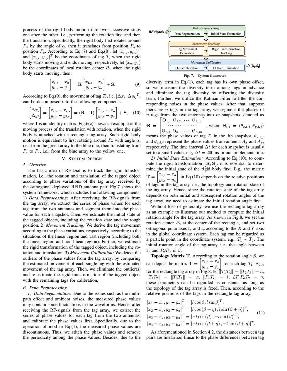
process of the rigid body motion into two successive steps Data Preprocessing RF-signals one after the other,i.e.,performing the rotation first and then Data Segmentation Initial State Estimation the translation.Specifically,the rigid body first rotates around Pa by the angle of o,then it translates from position Ps to Movement Tracking position P.According to Eq(7)and Eq.(8).letT Tag Movement Rigid Transformation Derivation and [T be the coordinates of tag T when the rigid Tracking body starts moving and ends moving,respectively,let(a,ya) Movement Calibration be the coordinates of local rotation center Pa when the rigid Outlier Detection Outlier Elimination [RS] body starts moving,then: Fig.7.System framework Ti,e -Fa=Ri-a +S. (9) diversity term in Eg.(1),each tag has its own phase offset, Vi,e-Va yi,s-Va so we measure the diversity term among tags in advance According to Eq.(9).the movement of tag Ti.e.[AAy and eliminate the tag diversity by offsetting the diversity term.Further,we utilize the Kalman Filter to filter the cor- can be decomposed into the following components: responding noises in the phase values.After that,suppose △xl Ti,e -Ti,s 工i,s-a there are n tags in the tag array,we segment the phases of (10) △y =(R-I) +S yi,e -Vi.s Vi,s-ya n tags from the two antennas into m snapshots,denoted as Θ1,1Θ1,2… 日1,m where I is an identity matrix.Fig.6(c)shows an example of the moving process of the translation with rotation,when the rigid whereθi,j=(0x,i,0y,i》 日n,1曰n.2… body is attached with a rectangle tag array.Such rigid body 日n,m」 means the phase values of tag Ti in the jth snapshot,0.i.j motion is equivalent to first rotating around Pa with angle o, and y.ii represent the phase values from antenna A and Ay. i.e.,from the green array to the blue one,then translating from respectively.The time interval At for each snapshot is usually P.to Pe,i.e.,from the blue array to the yellow one. set to a small value,e.g,At =200ms in our implementation. V.SYSTEM DESIGN 2)Initial State Estimation:According to Eq.(10),to com- A.Overview pute the rigid transformation R,S,it is essential to deter- The basic idea of RF-Dial is to track the rigid transfor- mine the initial state of the rigid body first.E.g.,the matrix mation,i.e.,the rotation and translation,of the tagged object T= Ti,s-Ta in Eq.(10)depends on the relative positions according to phase variations of the tag array received by yi.s-Ya the orthogonal deployed RFID antenna pair.Fig.7 shows the of tags in the tag array,i.e.,the topology and rotation state of system framework,which includes the following components: the tag array.Hence,since the rotation state of the tag array 1)Data Preprocessing:After receiving the RF-signals from depends on both initial and subsequent rotation angles of the the tag array,we extract the series of phase values for each tag array,we need to estimate the initial rotation angle first. tag from the two antennas and segment them into the phase Without loss of generality,we use the rectangle tag array value for each snapshot.Then,we estimate the initial state of as an example to illustrate our method to compute the initial the tagged objects,including the rotation state and the rough rotation angle for the tag array.As shown in Fig.8,we set the position.2)Movement Tracking:We derive the tag movement rotation center Pa at the center of the rectangle,and set two according to the phase variations,respectively,according to the orthogonal polar axes l and lu according to the X and Y-axis situations of the linear region and vast region(including both in the global coordinate system.Each tag can be regarded as the linear region and non-linear region).Further,we estimate a particle point in the coordinate system,e.g.,T~T.The the rigid transformation of the tagged object,including the ro- initial rotation angle of the tag array,i.e..the angle between tation and translation.3)Movement Calibration:We detect the Ir and PaTi,is B. outliers of the phase values from the tag array,by comparing Topology Matrix T.According to the rotation angle B,we the estimated movement of each single tag with the estimated can depict the matrix T= Ti,s -Ta 头,s-a for each tag Ti.E.g., movement of the tag array.Then,we eliminate the outlier(s) for the rectangle tag array in Fig.8,let TTll =T2T3 =h, and re-estimate the rigid transformation of the tagged object ITT2l=T3T4‖l=w,‖PaTl=l,LTiPaT2=n, with the remaining tags for calibration. these parameters can be regarded as constants,as long as B.Data Preprocessing the topology of the tag array is fixed.Then,according to the 1)Data Segmentation:Due to the issues such as the multi- relative positions of the tags in the rectangle tag array, path effect and ambient noises,the measured phase values may contain some fluctuations in the waveforms.Hence,after [F1-ta:y-ya]T [l cos B,Isin B]T, receiving the RF-signals from the tag array,we extract the [2-za:v2-ya]T [cos(B+n),lsin (8+n)]T, (11) series of phase values for each tag from the two antennas, [z3-za,y3-Va]T=[-l cos(B),-Isin (B)T, and calibrate the phase values first.Specifically,due to the operation of mod in Eq.(1),the measured phase values are [4-za:y4-ya]=[-l cos(B+n),-lsin (B+n)] discontinuous.Thus,we stitch the phase values and remove As aforementioned in Section 4.2,the distances between tag the periodicity among the phase values.Besides,due to the pairs are linear/non-linear to the phase differences between tagprocess of the rigid body motion into two successive steps one after the other, i.e., performing the rotation first and then the translation. Specifically, the rigid body first rotates around Pa by the angle of α, then it translates from position Ps to position Pe. According to Eq.(7) and Eq.(8), let [xi,s, yi,s] T and [xi,e, yi,e] T be the coordinates of tag Ti when the rigid body starts moving and ends moving, respectively, let (xa, ya) be the coordinates of local rotation center Pa when the rigid body starts moving, then: xi,e − xa yi,e − ya = R xi,s − xa yi,s − ya + S. (9) According to Eq.(9), the movement of tag Ti , i.e. [∆xi , ∆yi ] T , can be decomposed into the following components: ∆xi ∆yi = xi,e − xi,s yi,e − yi,s = (R − I) xi,s − xa yi,s − ya + S, (10) where I is an identity matrix. Fig.6(c) shows an example of the moving process of the translation with rotation, when the rigid body is attached with a rectangle tag array. Such rigid body motion is equivalent to first rotating around Pa with angle α, i.e., from the green array to the blue one, then translating from Ps to Pe, i.e., from the blue array to the yellow one. V. SYSTEM DESIGN A. Overview The basic idea of RF-Dial is to track the rigid transformation, i.e., the rotation and translation, of the tagged object according to phase variations of the tag array received by the orthogonal deployed RFID antenna pair. Fig.7 shows the system framework, which includes the following components: 1) Data Preprocessing: After receiving the RF-signals from the tag array, we extract the series of phase values for each tag from the two antennas and segment them into the phase value for each snapshot. Then, we estimate the initial state of the tagged objects, including the rotation state and the rough position. 2) Movement Tracking: We derive the tag movement according to the phase variations, respectively, according to the situations of the linear region and vast region (including both the linear region and non-linear region). Further, we estimate the rigid transformation of the tagged object, including the rotation and translation. 3) Movement Calibration: We detect the outliers of the phase values from the tag array, by comparing the estimated movement of each single tag with the estimated movement of the tag array. Then, we eliminate the outlier(s) and re-estimate the rigid transformation of the tagged object with the remaining tags for calibration. B. Data Preprocessing 1) Data Segmentation: Due to the issues such as the multipath effect and ambient noises, the measured phase values may contain some fluctuations in the waveforms. Hence, after receiving the RF-signals from the tag array, we extract the series of phase values for each tag from the two antennas, and calibrate the phase values first. Specifically, due to the operation of mod in Eq.(1), the measured phase values are discontinuous. Thus, we stitch the phase values and remove the periodicity among the phase values. Besides, due to the Data Preprocessing Movement Tracking Movement Calibration Outlier Detection Outlier Elimination Tag Movement Derivation Rigid Transformation Tracking Data Segmentation Initial State Estimation RF-signals ܜ܀] [ܜ܁ , Fig. 7. System framework diversity term in Eq.(1), each tag has its own phase offset, so we measure the diversity term among tags in advance and eliminate the tag diversity by offsetting the diversity term. Further, we utilize the Kalman Filter to filter the corresponding noises in the phase values. After that, suppose there are n tags in the tag array, we segment the phases of n tags from the two antennas into m snapshots, denoted as Θ = Θ1,1 Θ1,2 · · · Θ1,m · · · · · · · · · · · · Θn,1 Θn,2 · · · Θn,m , where Θi,j = hθx,i,j , θy,i,j i means the phase values of tag Ti in the jth snapshot, θx,i,j and θy,i,j represent the phase values from antenna Ax and Ay, respectively. The time interval ∆t for each snapshot is usually set to a small value, e.g, ∆t = 200ms in our implementation. 2) Initial State Estimation: According to Eq.(10), to compute the rigid transformation R, S , it is essential to determine the initial state of the rigid body first. E.g., the matrix T = xi,s − xa yi,s − ya in Eq.(10) depends on the relative positions of tags in the tag array, i.e., the topology and rotation state of the tag array. Hence, since the rotation state of the tag array depends on both initial and subsequent rotation angles of the tag array, we need to estimate the initial rotation angle first. Without loss of generality, we use the rectangle tag array as an example to illustrate our method to compute the initial rotation angle for the tag array. As shown in Fig.8, we set the rotation center Pa at the center of the rectangle, and set two orthogonal polar axes lx and ly according to the X and Y -axis in the global coordinate system. Each tag can be regarded as a particle point in the coordinate system, e.g., T1 ∼ T4. The initial rotation angle of the tag array, i.e., the angle between lx and PaT1, is β. Topology Matrix T. According to the rotation angle β, we can depict the matrix T = xi,s − xa yi,s − ya for each tag Ti . E.g., for the rectangle tag array in Fig.8, let kT1T4k = kT2T3k = h, kT1T2k = kT3T4k = w, kPaTik = l, 6 T1PaT2 = η, these parameters can be regarded as constants, as long as the topology of the tag array is fixed. Then, according to the relative positions of the tags in the rectangle tag array, [x1 − xa, y1 − ya] T = [l cos β, lsin β] T , [x2 − xa, y2 − ya] T = [l cos (β + η), lsin (β + η)]T , [x3 − xa, y3 − ya] T = [−l cos (β), −lsin (β)]T , [x4 − xa, y4 − ya] T = [−l cos (β + η), −lsin (β + η)]T . (11) As aforementioned in Section 4.2, the distances between tag pairs are linear/non-linear to the phase differences between tag��