正在加载图片...
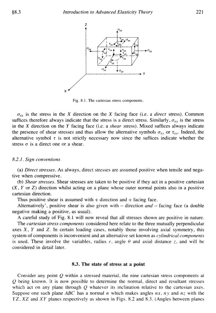
$8.3 Introduction to Advanced Elasticity Theory 221 0码 Fig.8.1.The cartesian stress components. or is the stress in the X direction on the X facing face (i.e.a direct stress).Common suffices therefore always indicate that the stress is a direct stress.Similarly,ory is the stress in the X direction on the Y facing face (i.e.a shear stress).Mixed suffices always indicate the presence of shear stresses and thus allow the alternative symbols osy or tx.Indeed,the alternative symbol t is not strictly necessary now since the suffices indicate whether the stress o is a direct one or a shear. 8.2.1.Sign conventions (a)Direct stresses.As always,direct stresses are assumed positive when tensile and nega- tive when compressive. (b)Shear stresses.Shear stresses are taken to be positive if they act in a positive cartesian (X.Y or Z)direction whilst acting on a plane whose outer normal points also in a positive cartesian direction. Thus positive shear is assumed with direction and facing face. Alternatively',positive shear is also given with-direction and-facing face (a double negative making a positive,as usual). A careful study of Fig.8.1 will now reveal that all stresses shown are positive in nature. The cartesian stress components considered here relate to the three mutually perpendicular axes X,Y and Z.In certain loading cases,notably those involving axial symmetry,this system of components is inconvenient and an alternative set known as cylindrical components is used.These involve the variables,radius r.angle 6 and axial distance z.and will be considered in detail later. 8.3.The state of stress at a point Consider any point O within a stressed material,the nine cartesian stress components at O being known.It is now possible to determine the normal,direct and resultant stresses which act on any plane through O whatever its inclination relative to the cartesian axes. Suppose one such plane ABC has a normal n which makes angles nx.ny and nz with the YZ.XZ and XY planes respectively as shown in Figs.8.2 and 8.3.(Angles between planes58.3 Introduction to Advanced Elasticity Theory -% Y 22 1 Fig. 8.1. The Cartesian stress components. a,, is the stress in the X direction on the X facing face (i.e. a direct stress). Common suffices therefore always indicate that the stress is a direct stress. Similarly, a,, is the stress in the X direction on the Y facing face (i.e. a shear stress). Mixed suffices always indicate the presence of shear stresses and thus allow the alternative symbols oxy or xx,. Indeed, the alternative symbol x is not strictly necessary now since the suffices indicate whether the stress a is a direct one or a shear. 8.2.1. Sign conventions (a) Direct stresses. As always, direct stresses are assumed positive when tensile and negative when compressive. (b) Shear stresses. Shear stresses are taken to be positive if they act in a positive Cartesian (X, Y or Z) direction whilst acting on a plane whose outer normal points also in a positive Cartesian direction. Thus positive shear is assumed with + direction and + facing face. Alternatively’, positive shear is also given with -- direction and - facing face (a double A careful study of Fig. 8.1 will now reveal that all stresses shown are positive in nature. The cartesian stress components considered here relate to the three mutually perpendicular axes X, Y and Z. In certain loading cases, notably those involving axial symmetry, this system of components is inconvenient and an alternative set known as cylindrical components is used. These involve the variables, radius r, angle 6 and axial distance z, and will be considered in detail later. negative making a positive, as usual). 83. The state of stress at a point Consider any point Q within a stressed material, the nine Cartesian stress components at Q being known. It is now possible to determine the normal, direct and resultant stresses which act on any plane through Q whatever its inclination relative to the Cartesian axes. Suppose one such plane ABC has a normal n which makes angles nx, ny and nz with the YZ, XZ and XY planes respectively as shown in Figs. 8.2 and 8.3. (Angles between planes