正在加载图片...
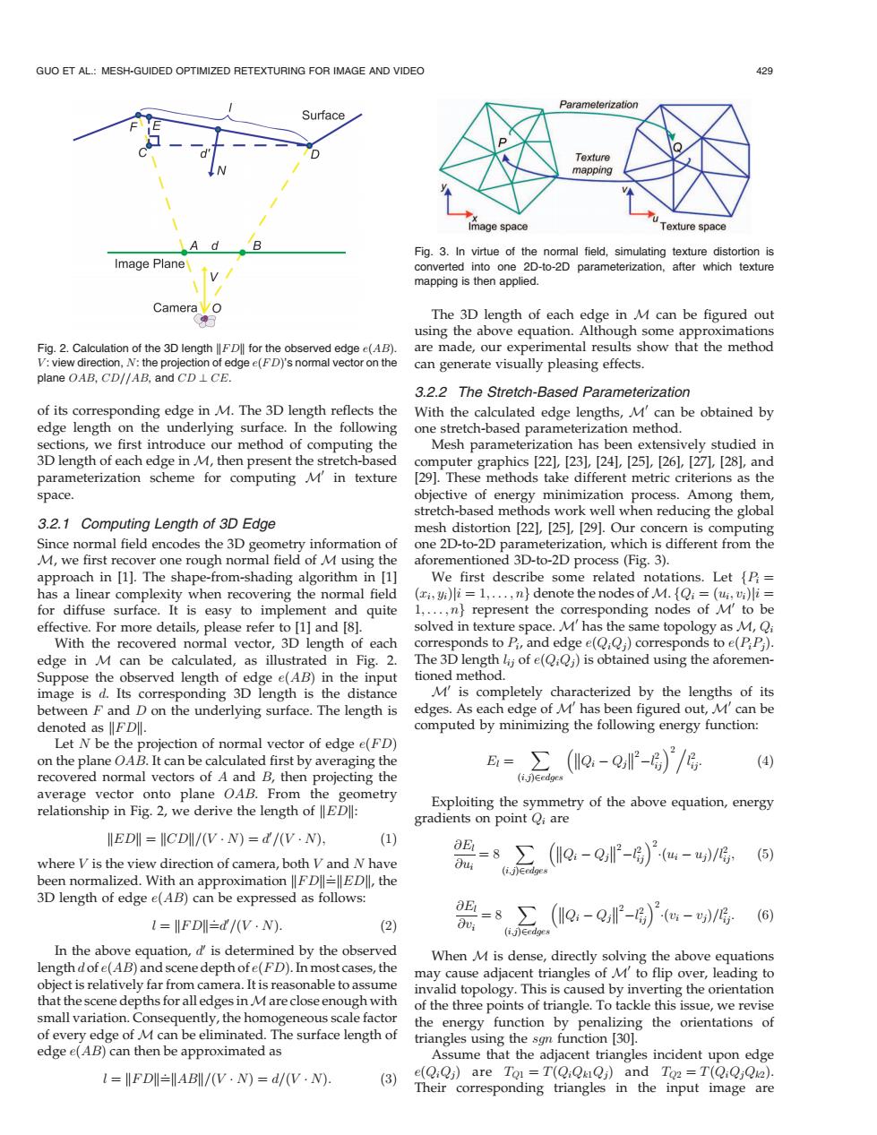
GUO ET AL.:MESH-GUIDED OPTIMIZED RETEXTURING FOR IMAGE AND VIDEO 429 Parameterization Surface Texture mapping VA Image space Texture space A d B Fig.3.In virtue of the normal field,simulating texture distortion is Image Plane converted into one 2D-to-2D parameterization,after which texture mapping is then applied. Camera The 3D length of each edge in M can be figured out using the above equation.Although some approximations Fig.2.Calculation of the 3D lengthFD for the observed edge e(AB). are made,our experimental results show that the method V:view direction,N:the projection of edge e(FD)'s normal vector on the can generate visually pleasing effects. plane OAB,CD//AB,and CD LCE. 3.2.2 The Stretch-Based Parameterization of its corresponding edge in M.The 3D length reflects the With the calculated edge lengths,M'can be obtained by edge length on the underlying surface.In the following one stretch-based parameterization method. sections,we first introduce our method of computing the Mesh parameterization has been extensively studied in 3D length of each edge in M,then present the stretch-based computer graphics [22],[23],[24],[25],[26],[271,[28],and parameterization scheme for computing M'in texture [29].These methods take different metric criterions as the space. objective of energy minimization process.Among them, stretch-based methods work well when reducing the global 3.2.1 Computing Length of 3D Edge mesh distortion [22],[25],[29].Our concern is computing Since normal field encodes the 3D geometry information of one 2D-to-2D parameterization,which is different from the M,we first recover one rough normal field of M using the aforementioned 3D-to-2D process(Fig.3). approach in [1].The shape-from-shading algorithm in [1] We first describe some related notations.Let {P= has a linear complexity when recovering the normal field (i,)i=1,...,n}denote the nodes of M.Qi =(ui,vi)li= for diffuse surface.It is easy to implement and quite 1,...,n}represent the corresponding nodes of M'to be effective.For more details,please refer to [1]and [8]. solved in texture space.M'has the same topology as M,Qi With the recovered normal vector,3D length of each corresponds to Pi,and edge e(QiQj)corresponds to e(PP) edge in M can be calculated,as illustrated in Fig.2.The 3D length lij of e(Q:Qj)is obtained using the aforemen- Suppose the observed length of edge e(AB)in the input tioned method. image is d.Its corresponding 3D length is the distance M'is completely characterized by the lengths of its between F and D on the underlying surface.The length is edges.As each edge of M'has been figured out,M'can be denoted as FDll. computed by minimizing the following energy function: Let N be the projection of normal vector of edge e(FD) on the plane OAB.It can be calculated first by averaging the =∑(Io-0-)/ (4) recovered normal vectors of A and B,then projecting the (i.j)Eedges average vector onto plane OAB.From the geometry relationship in Fig.2,we derive the length of ED: Exploiting the symmetry of the above equation,energy gradients on point Q;are IEDI=CDI/(V·N)=d/V·N): (1) where V is the view direction of camera,both V and N have B=8∑(le-0P-)°4-西/g, (i.j)Eedges been normalized.With an approximation FDEDIl,the 3D length of edge e(AB)can be expressed as follows: l=IFDI=d/(V·N) (2) 5=8∑(IlQ-Q,P-)°-/o (ij)Eedges In the above equation,d'is determined by the observed When M is dense,directly solving the above equations length dofe(AB)and scene depth ofe(FD).In most cases,the may cause adjacent triangles of M'to flip over,leading to object is relatively far from camera.It is reasonable to assume invalid topology.This is caused by inverting the orientation that the scene depths for all edges in M are close enough with of the three points of triangle.To tackle this issue,we revise small variation.Consequently,the homogeneous scale factor the energy function by penalizing the orientations of of every edge of M can be eliminated.The surface length of triangles using the sgn function [30]. edge e(AB)can then be approximated as Assume that the adjacent triangles incident upon edge FDABI/(V.N)=d/(V.N). (3) e(QiQj)are To =T(QiQRQj)and To2 =T(QiQjQ2). Their corresponding triangles in the input image areof its corresponding edge in M. The 3D length reflects the edge length on the underlying surface. In the following sections, we first introduce our method of computing the 3D length of each edge in M, then present the stretch-based parameterization scheme for computing M0 in texture space. 3.2.1 Computing Length of 3D Edge Since normal field encodes the 3D geometry information of M, we first recover one rough normal field of M using the approach in [1]. The shape-from-shading algorithm in [1] has a linear complexity when recovering the normal field for diffuse surface. It is easy to implement and quite effective. For more details, please refer to [1] and [8]. With the recovered normal vector, 3D length of each edge in M can be calculated, as illustrated in Fig. 2. Suppose the observed length of edge eðABÞ in the input image is d. Its corresponding 3D length is the distance between F and D on the underlying surface. The length is denoted as kFDk. Let N be the projection of normal vector of edge eðFDÞ on the plane OAB. It can be calculated first by averaging the recovered normal vectors of A and B, then projecting the average vector onto plane OAB. From the geometry relationship in Fig. 2, we derive the length of kEDk: kEDk¼kCDk=ðV NÞ ¼ d0 =ðV NÞ; ð1Þ where V is the view direction of camera, both V and N have been normalized. With an approximation kFDk¼: kEDk, the 3D length of edge eðABÞ can be expressed as follows: l ¼ kFDk¼: d0 =ðV NÞ: ð2Þ In the above equation, d0 is determined by the observed length d of eðABÞ and scene depth of eðFDÞ. In most cases, the object is relatively far from camera. It is reasonable to assume that the scene depths for all edges inMare close enough with small variation. Consequently, the homogeneous scale factor of every edge of M can be eliminated. The surface length of edge eðABÞ can then be approximated as l ¼ kFDk¼: kABk=ðV NÞ ¼ d=ðV NÞ: ð3Þ The 3D length of each edge in M can be figured out using the above equation. Although some approximations are made, our experimental results show that the method can generate visually pleasing effects. 3.2.2 The Stretch-Based Parameterization With the calculated edge lengths, M0 can be obtained by one stretch-based parameterization method. Mesh parameterization has been extensively studied in computer graphics [22], [23], [24], [25], [26], [27], [28], and [29]. These methods take different metric criterions as the objective of energy minimization process. Among them, stretch-based methods work well when reducing the global mesh distortion [22], [25], [29]. Our concern is computing one 2D-to-2D parameterization, which is different from the aforementioned 3D-to-2D process (Fig. 3). We first describe some related notations. Let fPi ¼ ðxi; yiÞji ¼ 1; ... ; ng denote the nodes of M. fQi ¼ ðui; viÞji ¼ 1; ... ; ng represent the corresponding nodes of M0 to be solved in texture space. M0 has the same topology as M, Qi corresponds to Pi, and edge eðQiQjÞ corresponds to eðPiPjÞ. The 3D length lij of eðQiQjÞ is obtained using the aforementioned method. M0 is completely characterized by the lengths of its edges. As each edge of M0 has been figured out, M0 can be computed by minimizing the following energy function: El ¼ X ði;jÞ2edges Qi Qj 2 l 2 ij 2. l 2 ij: ð4Þ Exploiting the symmetry of the above equation, energy gradients on point Qi are @El @ui ¼ 8 X ði;jÞ2edges Qi Qj 2 l 2 ij 2 ðui ujÞ=l2 ij; ð5Þ @El @vi ¼ 8 X ði;jÞ2edges Qi Qj 2 l 2 ij 2 ðvi vjÞ=l2 ij: ð6Þ When M is dense, directly solving the above equations may cause adjacent triangles of M0 to flip over, leading to invalid topology. This is caused by inverting the orientation of the three points of triangle. To tackle this issue, we revise the energy function by penalizing the orientations of triangles using the sgn function [30]. Assume that the adjacent triangles incident upon edge eðQiQjÞ are TQ1 ¼ TðQiQk1QjÞ and TQ2 ¼ TðQiQjQk2Þ. Their corresponding triangles in the input image are GUO ET AL.: MESH-GUIDED OPTIMIZED RETEXTURING FOR IMAGE AND VIDEO 429 Fig. 2. Calculation of the 3D length kFDk for the observed edge eðABÞ. V : view direction, N: the projection of edge eðFDÞ’s normal vector on the plane OAB, CD==AB, and CD ? CE. Fig. 3. In virtue of the normal field, simulating texture distortion is converted into one 2D-to-2D parameterization, after which texture mapping is then applied.������������������������������