正在加载图片...
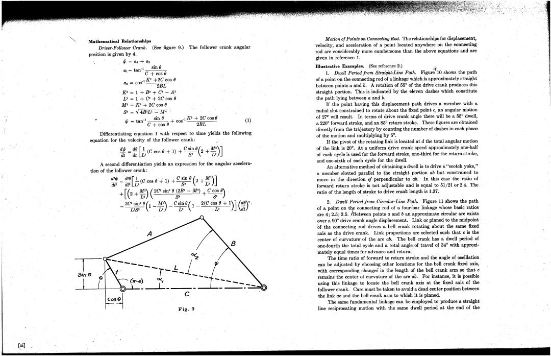
Mathematical Relationships Motion f Points on Connecting Rod.The relationships for displacement, Dricer-Follower Crank.(See figure 9.)The follower crank angular velocity,and acceleration of a point located anywhere on the connecting position is given by 4. rod are considerably more cumbersome than the above equations and are 业=a+a given in reference 1. gin 0 Illustrative Examples.(See reference 2.) a1-tan C+c080 1.Duell Period from Straigh-Line Path.Figure1 how the path a4=0gr1R+2C6089 of a point on the conneeting rod of a linkage which is approximately straight ·2BL between points a and b.A rotstion of 55 of the drive erank produces this K -1+B+C-A* straight portion.This is indieated by the eleven dashes which constitute L-1+Ci +2C cos 0 the path lying between a and b. =K*+2C cos 6 If the point having this displacement path drives a member with a S=√4BF-M radial slot constrained to rotate about the fixed point e,an angular motion -mce。+ow+Co0 sin 6 2BL ) of 279 will result.In terms of drive crank angle there will be a 55 dwell, a 220 forward stroke,and an 85 return stroke.These figures are obtained directly from the trajectory by counting the number of dashes in each phase Differentiating equation I with respeet to time yields the following equation for the velocity of the follower crank: of the motion and multiplying by 5. If the pivot of the rotating link is loeated at d the total angular motion 整-[cm0+)+c如+】] of the link is 20.At a uniform drive erank speed approximately one-half of each cyele is used for the forward stroke,one-third for the return stroke, A second differentintion yields an expression for the angular accelera- and one-sixth of ench eyele for the dwell. tion of the follower crank: An alternative method of obtaining a dwell is to drive s"sootch yoke," a member sotted parallel to the straight portion ab but constrained to 器-[品cm+)+0收+】 move in the direetion ef perpendicular to ab.In this case the ratio of +[+9)(2Ce-如+9 forward return stroke is not adjustable and is equal to 51/21 or 2.4.The ratio of the length of stroke to drive erank length is 1.37. -9-(-2+〗僧 2.Duell Period from Circular-Line Path.Figure 11 shows the path ofa point on the conneeting rod of a four-bar linknge whose basic ratios are 4;2.5;3.5./Between points a and b an approximate circular are exists over90 drive crank ange displneement.Link ae pinned to the midpoint of the conneeting rod drives a bell crank rotating about the same fixed axis as the drive erank.Link proportions are selected such that e is the center of curvature of the are ab.The bell erank has a dwell period of one-fourth the total cycle and a total angle of travel of 34 with approxi- mately oqual times for advance and return. The time ratio of forward to return stroke and the angle of oseillation ean be adjuated by choosing other locations for the bell crank fixed axis, with corresponding changes in the length of the bell crank arm so that c remains the center of curvature of the are a.For instance,it is poesible using this linkage to locate the bell crank axis at the fixed axis of the follower crank.Care must be taken to avoid a dead center position between the link ac and the bell crank arm to which it is pinned. Cos 6 The sme fundamental linkage can be employed to produce a straight F1g.9 line reciprocating motion with the same dwell period at the end of the 剪Mathematical Relationships Driver-Follower Crank. (See figure 9.) The follower crank ,angular position is given by 4. 1ft = alsin 8 al C+cos8 K2 +2C cos 8 a2 = cos 2BL K2 = 1 + B2 C2 = 1 + C2 2C cos 8 M'i K2 +2C cos 8 S2 ...J 4B2V M4 1. sin (j K2 2C cosO 'Y =, an cos + cos 8 2BL Differentiating equation 1 with respect to time yields the following equation for the velocity of the follower crank: (1) Motion of Points on Connecting Rod. The relationships for displacemen~, velocity, and acceleration of a point located anywhere on the connecting" r()d are considerably more cu~bersome than the above equations and are given in reference 1. IUustrative Exam les, (See reference 2. 1. DwellPeriod from Straight-Line Path. Figure 10 shows the path of a point on the connecting rod of a linkage which is approximately straight between points and b. A rotation of 550 of the drive crank produces this straight portion, This is indicated by the eleven dashes which constitute the path lying between and If the point having this displacement path drives a member with a radial slot constrained to rotate about the fixed point l;, an angular motion of 27P will result. In terms of drive crank angle there will be a 550 dwell a 2200 forward stroke, and an 850 return stroke. These figures are obtained directly from the trajectory by counting the number of dashes in each phase of the motion and multiplying by 50 If the pivot of the rotating link is located at the total angular motion of the link is 200. At a uniform drive crank speed approximately one-half of each cycle is used for the forward stroke, one~third for the return stroke and one-sixth of each cycle for the dwell. All alternative method of obtaining a dwell is to drive a "scotch yoke a member slotted parallel to the straight portion ab but constrained to move in the direction ef perpendicular to ab, In this case the ratio of forward return stroke is not adjustable" and is equal to 51/21 or 2,4. The ratio of the length of stroke to drive crank length is 1.37. d1ft (C cos 8 + 1) sin 8 2 + dt dt V S2 A second differentiation yields an expression for the angularaccelera- tion of the follower crank: " 1ft d28 l(Ccos 8 + 1) + sin 8 2 + dt2 dt2 V S2 202 sin2 8 (2B2 - M2) C cos 8 2C2 sin2 8 1 - sin 8 1 - 2(C cos 8 + I VS2 L2 OIC': , , "2 f/I ' -~ - ' ~ - - 6r~9) - ' - - Fig, 2. Dwell Period from Circular-Line Path. Figure 11 shows the path of a point on tbF connecting rod of a four-bar linkage whose basic ratios are 4; 2,5;3. 5. IBetween points andb an approximate circular arc exists over a 900 drive crank angle displacement, Link ac pinned to the midpoint of the connecting rod drives a bell crank rotating about the same fixed axis as the drive crank, Link proportions are selected such that is the center of curvature' of the arc ab. The bell crank has a dwell period of one-fourth the total cycle and a total angle of travel of 340 with approximately equal times for advance and return. The "time ratio of forward to return stroke and the angle of oscillation can be adjusted by choosing other locations for the bell crank fixed axis with corresponding changesin the length of the bell crank arm so that remains the center of curvature of the arc ab. For instance, it is possible using this linkage to locate the bell crank axis at the fixed axis of the follower crank, Care must be taken to avoid a dead center position between the iink ac and the" bell crank arm to which it is pillned. The same fundamental linkage can be employed to produce a straight line reciprocating motion with the same dwell period at the end of the (xi)