正在加载图片...

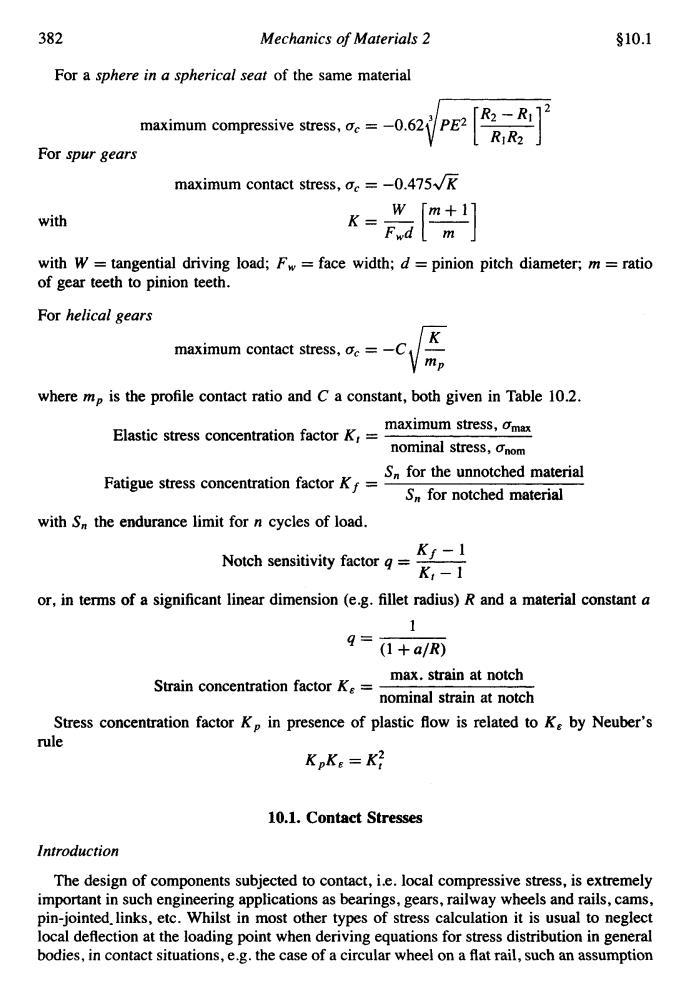
382 Mechanics of Materials 2 §10.1 For a sphere in a spherical seat of the same material maximum compressive stress,oc =-0.62 PE2 R2-R12 For spur gears maximum contact stress,oc=-0.475K W m+11 with K Fwd m with W tangential driving load;Fw=face width;d pinion pitch diameter;m=ratio of gear teeth to pinion teeth. For helical gears maximum contact stress,oc = mp where mp is the profile contact ratio and C a constant,both given in Table 10.2. Elastic stress concentration factor K,= maximum stress,Omax nominal stress,Onom Fatigue stress concentration factorK Sn for the unnotched material S for notched material with S the endurance limit for n cycles of load. Notch sensitivity factor K- K,-1 or,in terms of a significant linear dimension (e.g.fillet radius)R and a material constant a 1 9= (1+a/R) max.strain at notch Strain concentration factor Ke=- nominal strain at notch Stress concentration factor Kp in presence of plastic flow is related to Ke by Neuber's rule KpKe=K好 10.1.Contact Stresses Introduction The design of components subjected to contact,i.e.local compressive stress,is extremely important in such engineering applications as bearings,gears,railway wheels and rails,cams, pin-jointed.links,etc.Whilst in most other types of stress calculation it is usual to neglect local deflection at the loading point when deriving equations for stress distribution in general bodies,in contact situations,e.g.the case of a circular wheel on a flat rail,such an assumption382 Mechanics of Materials 2 $10.1 For a sphere in a spherical seat of the same material maximum compressive stress, a, = -0.62 For spur gears with maximum contact stress, a, = -0.475fi with W = tangential driving load; F, = face width; d = pinion pitch diameter; m = ratio of gear teeth to pinion teeth. For helical gears - maximum contact stress, a, = -C - \ifp where mp is the profile contact ratio and C a constant, both given in Table 10.2. maximum stress, amax nominal stress, anom Elastic stress concentration factor K, = S, for the unnotched material S, for notched material Fatigue stress concentration factor Kf = with S, the endurance limit for n cycles of load. Kf - 1 K, - 1 Notch sensitivity factor q = - or, in terms of a significant linear dimension (e.g. fillet radius) R and a material constant a 1 (1 + a/R) 4’ max. strain at notch nominal strain at notch Strain concentration factor K, = Stress concentration factor K, in presence of plastic flow is related to K, by Neuber’s rule K,K, = Kf 10.1. Contact Stresses Introduction The design of components subjected to contact, i.e. local compressive stress, is extremely important in such engineering applications as bearings, gears, railway wheels and rails, cams, pin-jointed-links, etc. Whilst in most other types of stress calculation it is usual to neglect local deflection at the loading point when deriving equations for stress distribution in general bodies, in contact situations, e.g. the case of a circular wheel on a flat rail, such an assumption