正在加载图片...

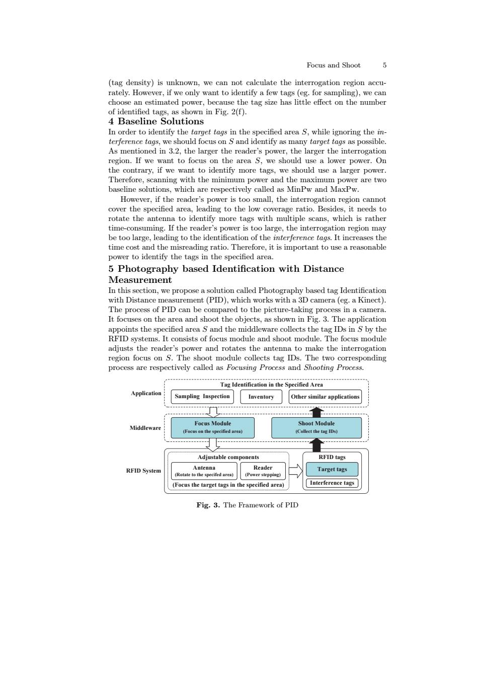
Focus and Shoot (tag density)is unknown,we can not calculate the interrogation region accu- rately.However,if we only want to identify a few tags (eg.for sampling),we can choose an estimated power,because the tag size has little effect on the number of identified tags,as shown in Fig.2(f). 4 Baseline Solutions In order to identify the target tags in the specified area s,while ignoring the in- terference tags,we should focus on S and identify as many target tags as possible. As mentioned in 3.2,the larger the reader's power,the larger the interrogation region.If we want to focus on the area S,we should use a lower power.On the contrary,if we want to identify more tags,we should use a larger power. Therefore,scanning with the minimum power and the maximum power are two baseline solutions,which are respectively called as MinPw and MaxPw. However,if the reader's power is too small,the interrogation region cannot cover the specified area.leading to the low coverage ratio.Besides,it needs to rotate the antenna to identify more tags with multiple scans,which is rather time-consuming.If the reader's power is too large,the interrogation region may be too large,leading to the identification of the interference tags.It increases the time cost and the misreading ratio.Therefore,it is important to use a reasonable power to identify the tags in the specified area. 5 Photography based Identification with Distance Measurement In this section,we propose a solution called Photography based tag Identification with Distance measurement(PID),which works with a 3D camera(eg.a Kinect). The process of PID can be compared to the picture-taking process in a camera. It focuses on the area and shoot the objects,as shown in Fig.3.The application appoints the specified area S and the middleware collects the tag IDs in S by the RFID systems.It consists of focus module and shoot module.The focus module adjusts the reader's power and rotates the antenna to make the interrogation region focus on S.The shoot module collects tag IDs.The two corresponding process are respectively called as Focusing Process and Shooting Process. Tag Identification in the Specified Area Application Sampling Inspection Inventory Other similar applications Focus Module Shoot Module Middlewar (Colleet the tag IDs) Adjustable components RFID tags RFID System Antenna Reader Target tags (Rotate to the specifed area) (Power stepping) (Focus the target tags in the specified area) Interference tags Fig.3.The Framework of PIDFocus and Shoot 5 (tag density) is unknown, we can not calculate the interrogation region accurately. However, if we only want to identify a few tags (eg. for sampling), we can choose an estimated power, because the tag size has little effect on the number of identified tags, as shown in Fig. 2(f). 4 Baseline Solutions In order to identify the target tags in the specified area S, while ignoring the interference tags, we should focus on S and identify as many target tags as possible. As mentioned in 3.2, the larger the reader’s power, the larger the interrogation region. If we want to focus on the area S, we should use a lower power. On the contrary, if we want to identify more tags, we should use a larger power. Therefore, scanning with the minimum power and the maximum power are two baseline solutions, which are respectively called as MinPw and MaxPw. However, if the reader’s power is too small, the interrogation region cannot cover the specified area, leading to the low coverage ratio. Besides, it needs to rotate the antenna to identify more tags with multiple scans, which is rather time-consuming. If the reader’s power is too large, the interrogation region may be too large, leading to the identification of the interference tags. It increases the time cost and the misreading ratio. Therefore, it is important to use a reasonable power to identify the tags in the specified area. 5 Photography based Identification with Distance Measurement In this section, we propose a solution called Photography based tag Identification with Distance measurement (PID), which works with a 3D camera (eg. a Kinect). The process of PID can be compared to the picture-taking process in a camera. It focuses on the area and shoot the objects, as shown in Fig. 3. The application appoints the specified area S and the middleware collects the tag IDs in S by the RFID systems. It consists of focus module and shoot module. The focus module adjusts the reader’s power and rotates the antenna to make the interrogation region focus on S. The shoot module collects tag IDs. The two corresponding process are respectively called as Focusing Process and Shooting Process. Sampling Inspection Inventory Tag Identification in the Specified Area Application Focus Module Shoot Module Middleware (Focus on the specified area) (Collect the tag IDs) Other similar applications RFID System RFID tags Target tags Interference tags Antenna (Rotate to the specifed area) Reader (Power stepping) Adjustable components (Focus the target tags in the specified area) Fig. 3. The Framework of PID