正在加载图片...
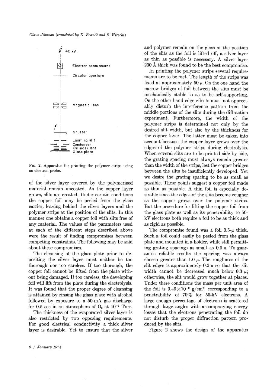
Claus Jonsson (translated by D.Brandt and S.Hirschi) and polymer remain on the glass at the position 40kV of the slits as the foil is lifted off,a silver layer as thin as possible is necessary.A silver layer Electron beam source 200 A thick was found to be the best compromise. In printing the polymer strips several require- Circular aperture ments are to be met.The length of the strips was fixed at approximately 50 4.On the one hand the narrow bridges of foil between the slits must be mechanically stable so as to be self-supporting. On the other hand edge effects must not appreci- Magnetic lens ably disturb the interference pattern from the middle portions of the slits during the diffraction experiment.Furthermore,the width of the polymer strips is determined not only by the Shutter desired slit width,but also by the thickness for the copper layer.The latter must be taken into Limiting slit Condenser account because the copper layer grows over the Cylinder lens edges of the polymer strips during electrolysis. Gloss plate When several slits are to be printed side by side, the grating spacing must always remain greater FIG.2.Apparatus for printing the polymer strips using than the width of the strips,lest the copper bridges an electron probe between the slits be insufficiently developed.Yet we desire the grating spacing to be as small as of the silver layer covered by the polymerized possible.These points suggest a copper foil made material remain uncoated.As the copper layer as thin as possible.A thin foil is especially de- grows,slits are created.Under certain conditions sirable since the edges of the slits become rougher the copper foil may be peeled from the glass as the copper grows over the polymer strips. carrier,leaving behind the silver layers and the But the procedure for lifting the copper foil from polymer strips at the position of the slits.In this the glass plate as well as its penetrability to 50- manner one obtains a copper foil with slits free of kV electrons both require a foil to be as thick and any material.The values of the parameters used as rigid as possible. at each of the different steps described above The compromise found was a foil 0.5-u thick. were the result of finding compromises between Such a foil could easily be peeled from the glass competing constraints.The following may be said plate and mounted in a holder,while still permitt- about these compromises. ing grating spacings as small as 0.9 g.To guar- The cleansing of the glass plate prior to de- antee reliable results the spacing was always positing the silver layer must neither be too chosen greater than 1.0 g.The roughness of the thorough nor too careless.If too thorough,the slit edges is approximately 0.2 so that the slit copper foil cannot be lifted from the plate with- width cannot be decreased much below 0.3 u; out being damaged.If too careless,the developing otherwise,the slit would grow together at places. foil will lift from the plate during the electrolysis. Under these conditions the mass per unit area of It was found that the proper degree of cleansing the foil is 0.45X10⁻³ g/cm2,corresponding to a is attained by rinsing the glass plate with alcohol penetrability of 70%for 50-kV electrons.A followed by exposure to a 50-mA gas discharge large enough percentage of electrons is scattered for 0.5 sec in an atmosphere of O2 at 10-*Torr. through large angles with accompanying energy The thickness of the evaporated silver layer is losses that the electrons penetrating the foil do also restricted by two opposing requirements. not disturb the proper diffraction pattern pro- For good electrical conductivity a thick silver duced by the slits. layer is desirable.Yet to ensure that the silver Figure 2 shows the design of the apparatus 6 January 197