正在加载图片...
a b Processing pore Carbonization Crack pore 200um 10um (c (d) Filled Semifilled Empty pore pore 40um 50μm Figure 7.3 Polarized-light micrographs of cross sections of unidirectional C-C composites showing different types of pores:(a)(b)undensified;and(c)-(d)densified composites.(See Color Plate IV) where pp is the density of the impregnant at room temperature,and p(0)the bulk density of the empty C-C composite.This expression can be generalized for the n-th step of impregnation as follows: Y(m)= △W(n)p(n-1) (2) 0(n-1)Pp Several factors,related not only to the experimental conditions used but also to the characteristics of the network of pores developed in the composite (Fig.7.3a)and the characteristics of the impregnant,affect the values of this parameter (Oh and Park,1994; Granda et al.,1998). The density of the carbon matrix of the final composite depends on the experimental con- ditions used in the carbonization step and may differ somewhat from the density obtained when the matrix precursor is carbonized alone under the same conditions.This is because in the composite the thermally induced stresses tend to promote additional graphitization and densification of both fiber and matrix(Rellick,1990). Another aspect that should be mentioned is the relationship between the weight gain of the composite in the impregnation and the absolute increase in weight due to the n-th cycle of densification.One might expect the ratio of these magnitudes to be the carbon yield of the matrix precursor under the processing conditions.However,this is not completely true, because when carbonization takes place after impregnation,the phenomenon of matrix bloating may occur as a consequence of the release of volatiles.As a result,matrix yields 2003 Taylor Franciswhere p is the density of the impregnant at room temperature, and (0) the bulk density of the empty C–C composite. This expression can be generalized for the n-th step of impregnation as follows: (2) Several factors, related not only to the experimental conditions used but also to the characteristics of the network of pores developed in the composite (Fig. 7.3a) and the characteristics of the impregnant, affect the values of this parameter (Oh and Park, 1994; Granda et al., 1998). The density of the carbon matrix of the final composite depends on the experimental conditions used in the carbonization step and may differ somewhat from the density obtained when the matrix precursor is carbonized alone under the same conditions. This is because in the composite the thermally induced stresses tend to promote additional graphitization and densification of both fiber and matrix (Rellick, 1990). Another aspect that should be mentioned is the relationship between the weight gain of the composite in the impregnation and the absolute increase in weight due to the n-th cycle of densification. One might expect the ratio of these magnitudes to be the carbon yield of the matrix precursor under the processing conditions. However, this is not completely true, because when carbonization takes place after impregnation, the phenomenon of matrix bloating may occur as a consequence of the release of volatiles. As a result, matrix yields Yi (n) Wi (n)
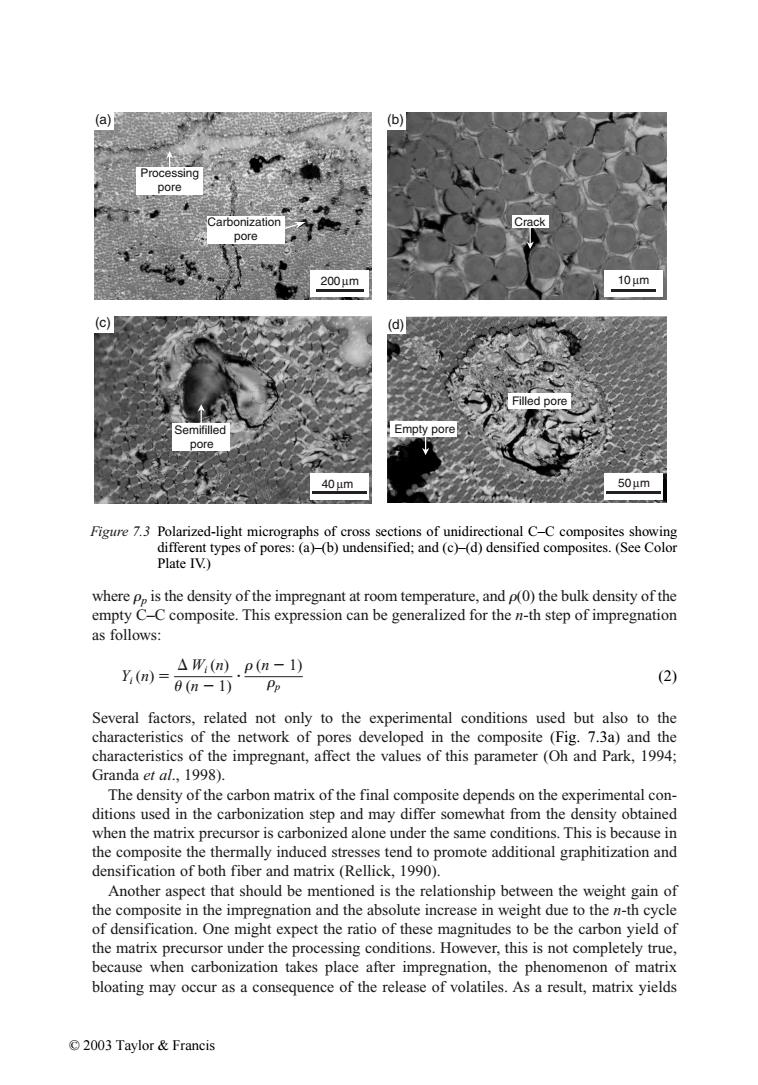
(n 1) (n 1) p Figure 7.3 Polarized-light micrographs of cross sections of unidirectional C–C composites showing different types of pores: (a)–(b) undensified; and (c)–(d) densified composites. (See Color Plate IV.) Crack 200 µm Carbonization pore Processing pore Semifilled pore Filled pore Empty pore 40 µm 50 µm 10 µm (a) (c) (b) (d) © 2003 Taylor & Francis����