正在加载图片...

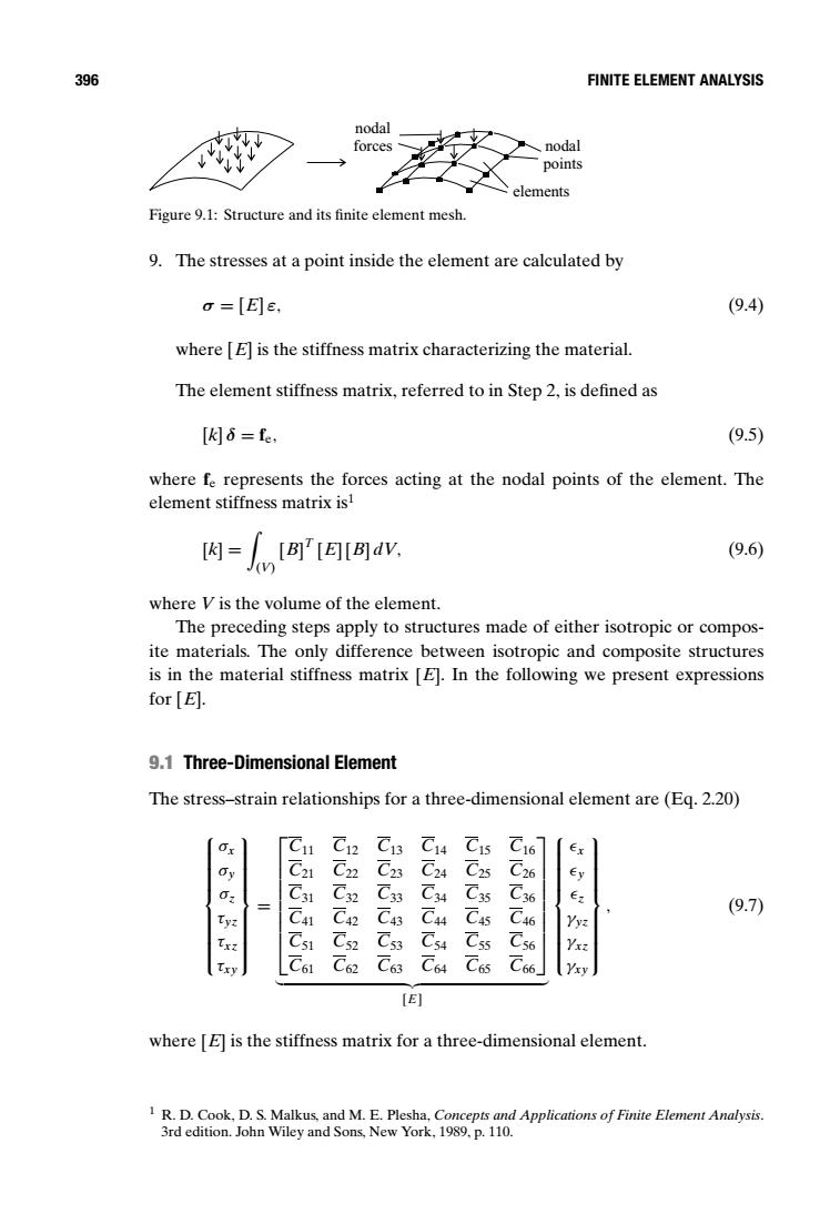
396 FINITE ELEMENT ANALYSIS nodal forces nodal points elements Figure 9.1:Structure and its finite element mesh. 9.The stresses at a point inside the element are calculated by =[E]E, (9.4) where [E]is the stiffness matrix characterizing the material. The element stiffness matrix,referred to in Step 2,is defined as [k6=e, (9.5) where fe represents the forces acting at the nodal points of the element.The element stiffness matrix is1 内=[A'A[Ba业 (9.6 where V is the volume of the element. The preceding steps apply to structures made of either isotropic or compos- ite materials.The only difference between isotropic and composite structures is in the material stiffness matrix [E].In the following we present expressions for [E]. 9.1 Three-Dimensional Element The stress-strain relationships for a three-dimensional element are(Eq.2.20) C11 C12 C13 C14 C15 C16 Ex 6 C21 C22 C23 C24 C25 C26 31 C32 C33 C34 C35 C36 y C C42 C43 C44 C45 C46 (9.7) C51 Cs2 C53 C54 Cs6 C61 C62 C63 C64 C65 C66 [E] where [E]is the stiffness matrix for a three-dimensional element. 1R.D.Cook,D.S.Malkus,and M.E.Plesha,Concepts and Applications of Finite Element Analysis 3rd edition.John Wiley and Sons,New York,1989.p.110.396 FINITE ELEMENT ANALYSIS nodal forces nodal points elements Figure 9.1: Structure and its finite element mesh. 9. The stresses at a point inside the element are calculated by σ = [E] ε, (9.4) where [E] is the stiffness matrix characterizing the material. The element stiffness matrix, referred to in Step 2, is defined as [k] δ = fe, (9.5) where fe represents the forces acting at the nodal points of the element. The element stiffness matrix is1 [k] = ) (V) [B] T [E] [B] dV, (9.6) where V is the volume of the element. The preceding steps apply to structures made of either isotropic or composite materials. The only difference between isotropic and composite structures is in the material stiffness matrix [E]. In the following we present expressions for [E]. 9.1 Three-Dimensional Element The stress–strain relationships for a three-dimensional element are (Eq. 2.20) σx σy σz τyz τxz τxy = C11 C12 C13 C14 C15 C16 C21 C22 C23 C24 C25 C26 C31 C32 C33 C34 C35 C36 C41 C42 C43 C44 C45 C46 C51 C52 C53 C54 C55 C56 C61 C62 C63 C64 C65 C66 % &' ( [E] x y z γyz γxz γxy , (9.7) where [E] is the stiffness matrix for a three-dimensional element. 1 R. D. Cook, D. S. Malkus, and M. E. Plesha, Concepts and Applications of Finite Element Analysis. 3rd edition. John Wiley and Sons, New York, 1989, p. 110