正在加载图片...
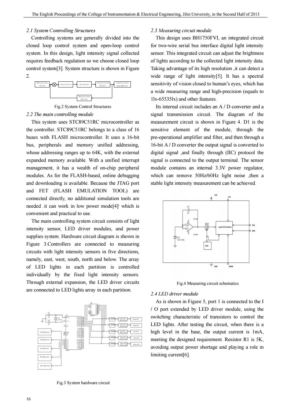
The English Proceedings of the College of Instrumentation&Electrical Engineeringn University,in the Second Half of 2013 2.1 System Controlling Sructures Controlling systems are generally divided into the This design uses BH1750FVI,an integrated circuit closed loop control system and open-loop control for two-wire serial bus interface digital light intensity system.In this design,light intensity signal collected sensor.This integrated circuit can adjust the brightness requires feedback regulation so we choose closed loot of lights according to the collected light intensity data. ontro system[3].System structure is shown in Figun Taking advant wide range of light intensity[5].It has a spectral ⑧-网-a巴□ sensitivity of vision closed to human's eyes,which has a wide measuring range and high-precision(equals to 回 1lx-655351x)and other features Its inteal iruit/Dconverterand 2.2 The main controlling module signal transmission circuit.The diagram of the This system uses STC89C5IRC microcontroller as measurement circuit is shown in Figure 4.DI is the the controller.STC89C5IRC belongs to a class of 16 sensitive element of the module.through the buses with FLASH microcontroller.It uses a 16-bit pre-operational amplifier and filter,and then through a bus.peripherals and memory unified addressing 16-bitA/D converter the ouput signal is convertedto 4K,with the extema digital signal and finally through (IIC expanded memory available.With a unified interrupt signal is connected to the output terminal.The sensor management,it has a wealth of on-chip peripheral module contains an internal 3.3V power regulator modules.As for the FLASH-based,online debugging which can remove 50Hz/60Hz light noise ,then a and downloading is available.Because the JTAG port stable light intensity measurement can be achieved. and FET (FLASH EMULATION connected directly,no additional simulation tools are needed.it can work in low power modef4]'which is convenient and practical to use. The main controlling system circuit consists of ligh intensity sensor,LED driver modules,and powe Figure 3.Controllers are connected to measuring circuits with light intensity sensors in five directions namely,east,west,south,north and below.The array of LED lights in each partition is controlled individually Through extemal expansion,the LED driver circuits Fig 4 Measuring circuit schematics are connected to LED lights array in each partition. 2.4 LED driver module As is shown in Figure 5.port 1 is connected to the I port extended by LED driver module,using the switching characteristic of transistors to contro the LED lights.After testing the circuit,when there is a high level in the base,the output current is 1mA meeting the designed requirement.Resistor RI is 5K, avoiding output power shortage and playing a role in limiting current6]. Fig3 System hardware ciru 16 期 The English Proceedings of the College of Instrumentation & Electrical Engineering, Jilin University, in the Second Half of 2013 16 2.1 System Controlling Structures Controlling systems are generally divided into the closed loop control system and open-loop control system. In this design, light intensity signal collected requires feedback regulation so we choose closed loop control system[3]. System structure is shown in Figure 2. Fig.2 System Control Structures 2.2 The main controlling module This system uses STC89C51RC microcontroller as the controller. STC89C51RC belongs to a class of 16 buses with FLASH microcontroller. It uses a 16-bit bus, peripherals and memory unified addressing, whose addressing ranges up to 64K, with the external expanded memory available. With a unified interrupt management, it has a wealth of on-chip peripheral modules. As for the FLASH-based, online debugging and downloading is available. Because the JTAG port and FET (FLASH EMULATION TOOL) are connected directly, no additional simulation tools are needed .it can work in low power mode[4], which is convenient and practical to use. The main controlling system circuit consists of light intensity sensor, LED driver modules, and power supplies system. Hardware circuit diagram is shown in Figure 3.Controllers are connected to measuring circuits with light intensity sensors in five directions, namely, east, west, south, north and below. The array of LED lights in each partition is controlled individually by the fixed light intensity sensors. Through external expansion, the LED driver circuits are connected to LED lights array in each partition. Fig.3 System hardware circuit 2.3 Measuring circuit module This design uses BH1750FVI, an integrated circuit for two-wire serial bus interface digital light intensity sensor. This integrated circuit can adjust the brightness of lights according to the collected light intensity data. Taking advantage of its high resolution ,it can detect a wide range of light intensity[5]. It has a spectral sensitivity of vision closed to human’s eyes, which has a wide measuring range and high-precision (equals to 1lx-65535lx) and other features. Its internal circuit includes an A / D converter and a signal transmission circuit. The diagram of the measurement circuit is shown in Figure 4. D1 is the sensitive element of the module, through the pre-operational amplifier and filter, and then through a 16-bit A / D converter the output signal is converted to digital signal ,and finally through (IIC) protocol the signal is connected to the output terminal. The sensor module contains an internal 3.3V power regulator, which can remove 50Hz/60Hz light noise ,then a stable light intensity measurement can be achieved. Fig.4 Measuring circuit schematics 2.4 LED driver module As is shown in Figure 5, port 1 is connected to the I / O port extended by LED driver module, using the switching characteristic of transistors to control the LED lights. After testing the circuit, when there is a high level in the base, the output current is 1mA, meeting the designed requirement. Resistor R1 is 5K, avoiding output power shortage and playing a role in limiting current[6]