正在加载图片...
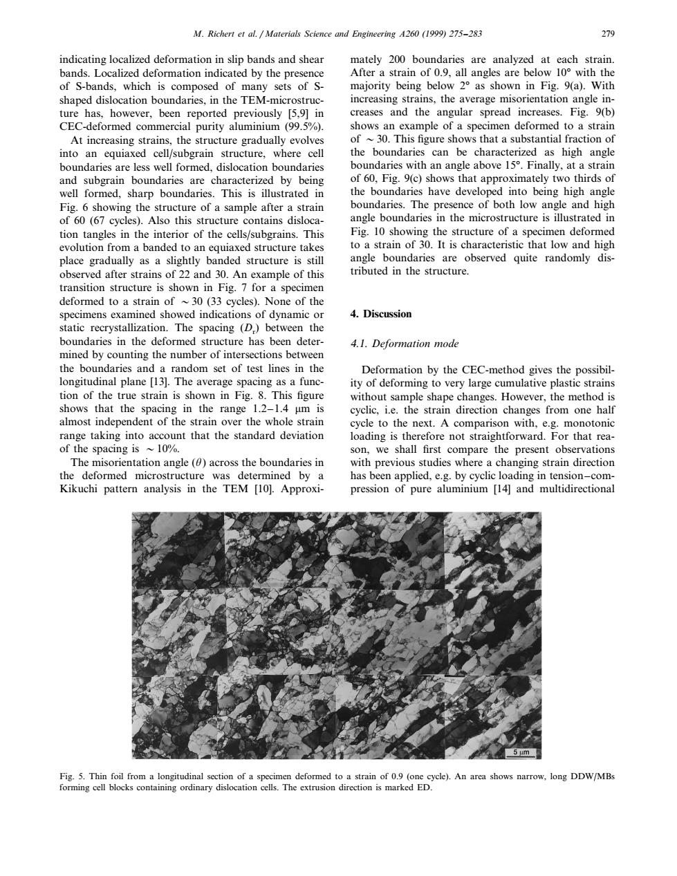
M.Richert et al.Materials Science and Engineering A260 (1999)275-283 279 indicating localized deformation in slip bands and shear mately 200 boundaries are analyzed at each strain bands.Localized deformation indicated by the presence After a strain of 0.9.all angles are below 10 with the of S-bands,which is composed of many sets of S- majority being below 2 as shown in Fig.9(a).With shaped dislocation boundaries,in the TEM-microstruc- increasing strains.the average misorientation angle in- ture has,however,been reported previously [5,9]in creases and the angular spread increases.Fig.9(b) CEC-deformed commercial purity aluminium (99.5%). shows an example of a specimen deformed to a strain At increasing strains,the structure gradually evolves of ~30.This figure shows that a substantial fraction of into an equiaxed cell/subgrain structure,where cell the boundaries can be characterized as high angle boundaries are less well formed,dislocation boundaries boundaries with an angle above 15.Finally,at a strain and subgrain boundaries are characterized by being of 60,Fig.9(c)shows that approximately two thirds of well formed,sharp boundaries.This is illustrated in the boundaries have developed into being high angle Fig.6 showing the structure of a sample after a strain boundaries.The presence of both low angle and high of 60(67 cycles).Also this structure contains disloca- angle boundaries in the microstructure is illustrated in tion tangles in the interior of the cells/subgrains.This Fig.10 showing the structure of a specimen deformed evolution from a banded to an equiaxed structure takes to a strain of 30.It is characteristic that low and high place gradually as a slightly banded structure is still angle boundaries are observed quite randomly dis- observed after strains of 22 and 30.An example of this tributed in the structure. transition structure is shown in Fig.7 for a specimen deformed to a strain of ~30(33 cycles).None of the specimens examined showed indications of dynamic or 4.Discussion static recrystallization.The spacing (D)between the boundaries in the deformed structure has been deter- 4.1.Deformation mode mined by counting the number of intersections between the boundaries and a random set of test lines in the Deformation by the CEC-method gives the possibil- longitudinal plane [13].The average spacing as a func- ity of deforming to very large cumulative plastic strains tion of the true strain is shown in Fig.8.This figure without sample shape changes.However,the method is shows that the spacing in the range 1.2-1.4 um is cyclic,i.e.the strain direction changes from one half almost independent of the strain over the whole strain cycle to the next.A comparison with,e.g.monotonic range taking into account that the standard deviation loading is therefore not straightforward.For that rea- of the spacing is ~10%. son,we shall first compare the present observations The misorientation angle (0)across the boundaries in with previous studies where a changing strain direction the deformed microstructure was determined by a has been applied,e.g.by cyclic loading in tension-com- Kikuchi pattern analysis in the TEM [10].Approxi- pression of pure aluminium [14]and multidirectional Fig.5.Thin foil from a longitudinal section of a specimen deformed to a strain of 0.9 (one cycle).An area shows narrow,long DDW/MBs forming cell blocks containing ordinary dislocation cells.The extrusion direction is marked ED.M. Richert et al. / Materials Science and Engineering A260 (1999) 275–283 279 indicating localized deformation in slip bands and shear bands. Localized deformation indicated by the presence of S-bands, which is composed of many sets of Sshaped dislocation boundaries, in the TEM-microstructure has, however, been reported previously [5,9] in CEC-deformed commercial purity aluminium (99.5%). At increasing strains, the structure gradually evolves into an equiaxed cell/subgrain structure, where cell boundaries are less well formed, dislocation boundaries and subgrain boundaries are characterized by being well formed, sharp boundaries. This is illustrated in Fig. 6 showing the structure of a sample after a strain of 60 (67 cycles). Also this structure contains dislocation tangles in the interior of the cells/subgrains. This evolution from a banded to an equiaxed structure takes place gradually as a slightly banded structure is still observed after strains of 22 and 30. An example of this transition structure is shown in Fig. 7 for a specimen deformed to a strain of 30 (33 cycles). None of the specimens examined showed indications of dynamic or static recrystallization. The spacing (Dr) between the boundaries in the deformed structure has been determined by counting the number of intersections between the boundaries and a random set of test lines in the longitudinal plane [13]. The average spacing as a function of the true strain is shown in Fig. 8. This figure shows that the spacing in the range 1.2–1.4 mm is almost independent of the strain over the whole strain range taking into account that the standard deviation of the spacing is 10%. The misorientation angle (u) across the boundaries in the deformed microstructure was determined by a Kikuchi pattern analysis in the TEM [10]. Approximately 200 boundaries are analyzed at each strain. After a strain of 0.9, all angles are below 10° with the majority being below 2° as shown in Fig. 9(a). With increasing strains, the average misorientation angle increases and the angular spread increases. Fig. 9(b) shows an example of a specimen deformed to a strain of 30. This figure shows that a substantial fraction of the boundaries can be characterized as high angle boundaries with an angle above 15°. Finally, at a strain of 60, Fig. 9(c) shows that approximately two thirds of the boundaries have developed into being high angle boundaries. The presence of both low angle and high angle boundaries in the microstructure is illustrated in Fig. 10 showing the structure of a specimen deformed to a strain of 30. It is characteristic that low and high angle boundaries are observed quite randomly distributed in the structure. 4. Discussion 4.1. Deformation mode Deformation by the CEC-method gives the possibility of deforming to very large cumulative plastic strains without sample shape changes. However, the method is cyclic, i.e. the strain direction changes from one half cycle to the next. A comparison with, e.g. monotonic loading is therefore not straightforward. For that reason, we shall first compare the present observations with previous studies where a changing strain direction has been applied, e.g. by cyclic loading in tension–compression of pure aluminium [14] and multidirectional Fig. 5. Thin foil from a longitudinal section of a specimen deformed to a strain of 0.9 (one cycle). An area shows narrow, long DDW/MBs forming cell blocks containing ordinary dislocation cells. The extrusion direction is marked ED.���