正在加载图片...
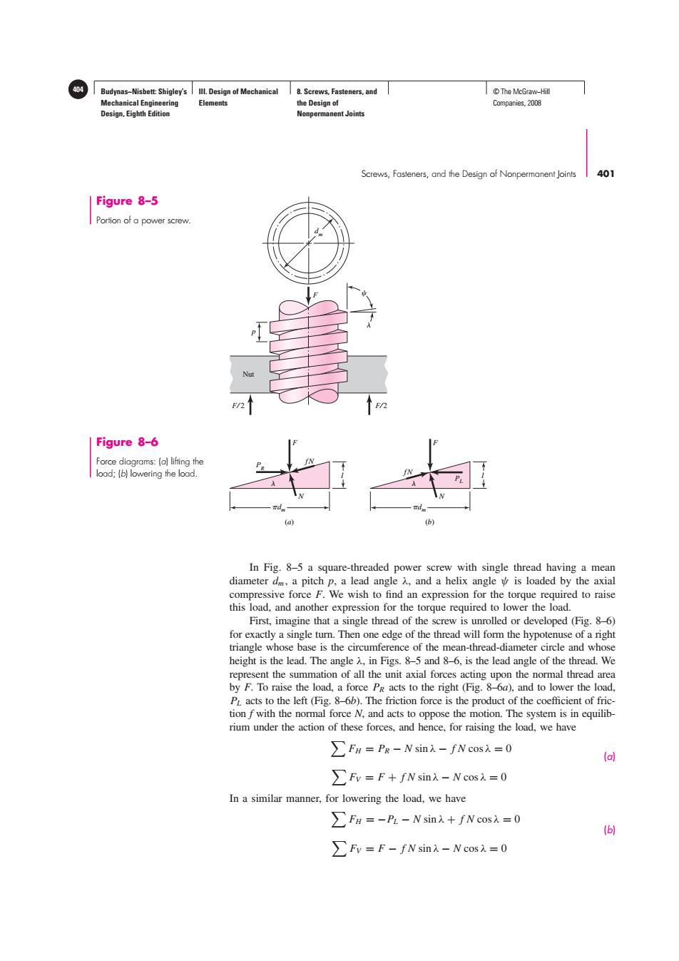
404 Budynas-Nisbett:Shigley's Ill.Design of Mechanical 8.Screws,Fasteners,and T©The McGraw-Hil Mechanical Engineering Elements the Design of Companies,2008 Design,Eighth Edition Nonpermanent Joints Screws,Fasteners,and the Design of Nonpermanent Joints 401 Figure 8-5 Portion of a power screw. F/2 Figure 8-6 Force diagrams:(a)lifting the load;(b)lowering the lood. (B) In Fig.8-5 a square-threaded power screw with single thread having a mean diameter dm,a pitch p,a lead angle and a helix angle is loaded by the axial compressive force F.We wish to find an expression for the torque required to raise this load,and another expression for the torque required to lower the load. First,imagine that a single thread of the screw is unrolled or developed (Fig.8-6) for exactly a single turn.Then one edge of the thread will form the hypotenuse of a right triangle whose base is the circumference of the mean-thread-diameter circle and whose height is the lead.The angle A,in Figs.8-5 and 8-6,is the lead angle of the thread.We represent the summation of all the unit axial forces acting upon the normal thread area by F.To raise the load,a force Pg acts to the right (Fig.8-6a),and to lower the load, PL acts to the left(Fig.8-6b).The friction force is the product of the coefficient of fric- tion fwith the normal force N,and acts to oppose the motion.The system is in equilib- rium under the action of these forces,and hence,for raising the load,we have >Fn PR-N sin).-fN cos=0 (a) >Fv=F+fN sinx-N cos=0 In a similar manner,for lowering the load,we have ∑FH=-PL-Nsin入+fN cosi入=0 6 ∑Fv=F-fNsin-Ncos入=0Budynas−Nisbett: Shigley’s Mechanical Engineering Design, Eighth Edition III. Design of Mechanical Elements 8. Screws, Fasteners, and the Design of Nonpermanent Joints 404 © The McGraw−Hill Companies, 2008 Screws, Fasteners, and the Design of Nonpermanent Joints 401 F⁄ 2 p F F⁄ 2 Nut dm Figure 8–5 Portion of a power screw. dm l F PR fN N dm (a) (b) l F fN PL N Figure 8–6 Force diagrams: (a) lifting the load; (b) lowering the load. In Fig. 8–5 a square-threaded power screw with single thread having a mean diameter dm , a pitch p, a lead angle λ, and a helix angle ψ is loaded by the axial compressive force F. We wish to find an expression for the torque required to raise this load, and another expression for the torque required to lower the load. First, imagine that a single thread of the screw is unrolled or developed (Fig. 8–6) for exactly a single turn. Then one edge of the thread will form the hypotenuse of a right triangle whose base is the circumference of the mean-thread-diameter circle and whose height is the lead. The angle λ, in Figs. 8–5 and 8–6, is the lead angle of the thread. We represent the summation of all the unit axial forces acting upon the normal thread area by F. To raise the load, a force PR acts to the right (Fig. 8–6a), and to lower the load, PL acts to the left (Fig. 8–6b). The friction force is the product of the coefficient of friction f with the normal force N, and acts to oppose the motion. The system is in equilibrium under the action of these forces, and hence, for raising the load, we have FH = PR − N sin λ − f N cos λ = 0 (a) FV = F + f N sin λ − N cos λ = 0 In a similar manner, for lowering the load, we have FH = −PL − N sin λ + f N cos λ = 0 (b) FV = F − f N sin λ − N cos λ = 0��������