正在加载图片...
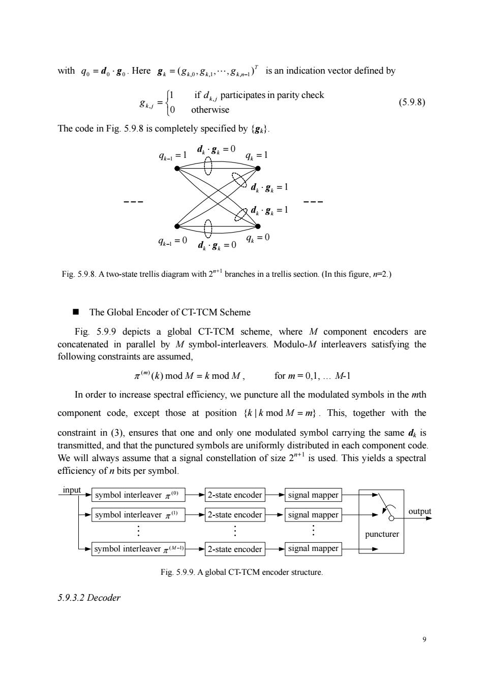
with odgHereg=(g)is an indication vector defined by [1 ifd participates in parity check g0 otherwise (5.9.8) The code in Fig.5.9.8 is completely specified by 91-1 d:8=0 9=1 - 久484=1 0 9=0g=0=0 Fig.5.9.8.Atwo-state trellis diagram with2branches in a trellis section.(In this figure,n.) The Global Encoder of CT-TCM Scheme Fig.5.9.9 depicts a global CT-TCM scheme,where M component encoders are concatenated in parallel by M symbol-interleavers.Modulo-M interleavers satisfying the ts are assumed, π(k)modM=k mod M, for m=0,1.M In order to increase spectral efficiency,we puncture all the modulated symbols in the mth component code,except those at positionk mod M=m).This,together with the constraint in(3),ensures that one and only one modulated symbol carrying the same d is transmitted,and that the punctured symbols are uniformly distributed in each component code We will always assume that a signal constellation of size 2"is used.This yields a spectral efficiency of n bits per symbol. input symbol interleaver2-state encodersignal mapper symbol interleaver 2-state encoder →signal mapper symbol interleaver 2-state encodersignal mapper Fig 5.9.9.A global CT-TCM encoder structure 5.9.3.2 Decoder 9 9 with 0 d0 g0 q = ⋅ . Here T k k k k n (g , g , , g ) = ,0 ,1 " , −1 g is an indication vector defined by ⎩ ⎨ ⎧ = 0 otherwise 1 if , participatesin parity check , k j k j d g (5.9.8) The code in Fig. 5.9.8 is completely specified by {gk}. 1 qk−1 = = 1 k q qk−1 = 0 qk = 0 dk ⋅ gk = 1 dk ⋅ gk = 0 dk ⋅ gk = 0 ⋅ = 1 k k d g Fig. 5.9.8. A two-state trellis diagram with 2n+1 branches in a trellis section. (In this figure, n=2.) The Global Encoder of CT-TCM Scheme Fig. 5.9.9 depicts a global CT-TCM scheme, where M component encoders are concatenated in parallel by M symbol-interleavers. Modulo-M interleavers satisfying the following constraints are assumed, k M k M m ( ) mod mod ( ) π = , for m = 0,1, . M-1 In order to increase spectral efficiency, we puncture all the modulated symbols in the mth component code, except those at position } {k | k mod M = m . This, together with the constraint in (3), ensures that one and only one modulated symbol carrying the same dk is transmitted, and that the punctured symbols are uniformly distributed in each component code. We will always assume that a signal constellation of size 2n+1 is used. This yields a spectral efficiency of n bits per symbol. 2-state encoder (M −1) symbol interleaver π signal mapper puncturer output input 2-state encoder (1) symbol interleaver signal mapper π 2-state encoder (0) symbol interleaver π signal mapper Fig. 5.9.9. A global CT-TCM encoder structure. 5.9.3.2 Decoder