正在加载图片...

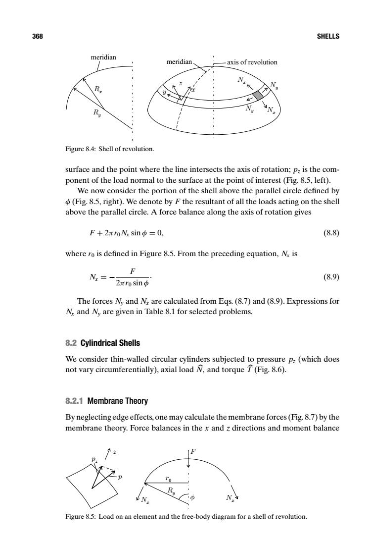
368 SHELLS meridian meridian -axis of revolution Figure 8.4:Shell of revolution. surface and the point where the line intersects the axis of rotation;p:is the com- ponent of the load normal to the surface at the point of interest (Fig.8.5,left). We now consider the portion of the shell above the parallel circle defined by (Fig.8.5,right).We denote by F the resultant of all the loads acting on the shell above the parallel circle.A force balance along the axis of rotation gives F+2rroN.sin中=0, (8.8) where ro is defined in Figure 8.5.From the preceding equation,N is F N=- (8.9) 2xro sin The forces Ny and Nx are calculated from Eqs.(8.7)and(8.9).Expressions for M and N,are given in Table 8.1 for selected problems. 8.2 Cylindrical Shells We consider thin-walled circular cylinders subjected to pressure pa(which does not vary circumferentially),axial load N,and torque T(Fig.8.6). 8.2.1 Membrane Theory By neglecting edge effects,one may calculate the membrane forces(Fig.8.7)by the membrane theory.Force balances in the x and z directions and moment balance N N Figure 8.5:Load on an element and the free-body diagram for a shell of revolution.368 SHELLS z x Nx Nx Ny Ny y Ry Rx meridian meridian axis of revolution Figure 8.4: Shell of revolution. surface and the point where the line intersects the axis of rotation; pz is the component of the load normal to the surface at the point of interest (Fig. 8.5, left). We now consider the portion of the shell above the parallel circle defined by φ (Fig. 8.5, right). We denote by F the resultant of all the loads acting on the shell above the parallel circle. A force balance along the axis of rotation gives F + 2πr0Nx sin φ = 0, (8.8) where r0 is defined in Figure 8.5. From the preceding equation, Nx is Nx = − F 2πr0 sin φ . (8.9) The forces Ny and Nx are calculated from Eqs. (8.7) and (8.9). Expressions for Nx and Ny are given in Table 8.1 for selected problems. 8.2 Cylindrical Shells We consider thin-walled circular cylinders subjected to pressure pz (which does not vary circumferentially), axial load N, and torque T (Fig. 8.6). 8.2.1 Membrane Theory By neglecting edge effects, one may calculate the membrane forces (Fig. 8.7) by the membrane theory. Force balances in the x and z directions and moment balance Nx Nx Ry φ r0 F p pz z Figure 8.5: Load on an element and the free-body diagram for a shell of revolution