正在加载图片...
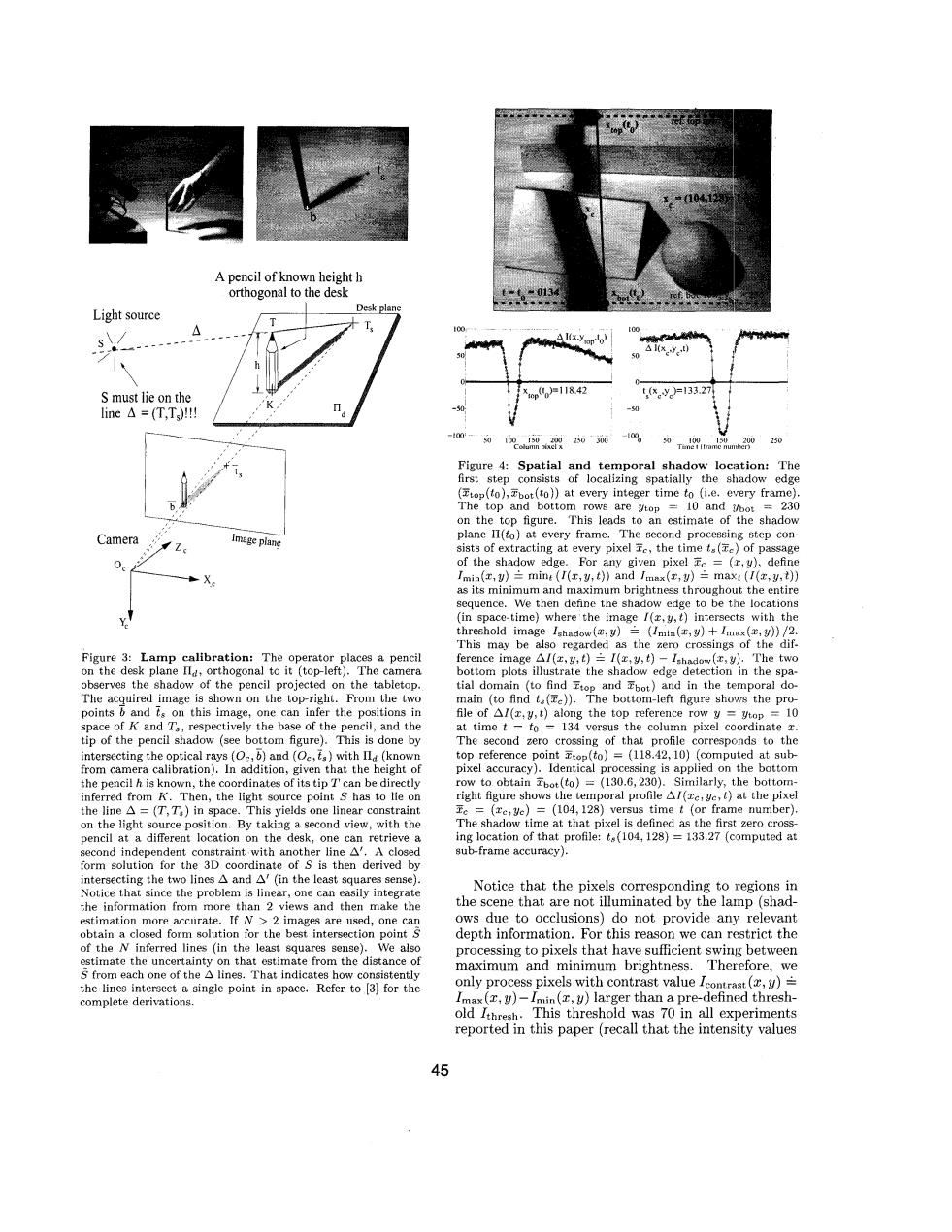
A pencil of known height h orthogonal to the desk 0131 Light source Desk plane △1(xy0 S must lie on the x0po=118.42 x.y=133.27 ine△=(T,Ts! 400- 0 250 Figure 4:Spatial and temporal shadow location:The first step consists of localizing spatially the shadow edge (to(to),bot(to))at every integer time to (i.e.every frame). The top and bottom rows are ytop =10 and =230 on the top figure.This leads to an estimate of the shadow Camera Image plane plane l1(to)at every frame.The second processing step con- Z sists of extracting at every pixel c,the time ts(Te)of passage of the shadow edge.For any given pixel c=(r,y),define Imin(x,)三mint(I(x,y,t)and /max(x,)兰max:(I(x,y,t) as its minimum and maximum brightness throughout the entire sequence.We then define the shadow edge to be the locations (in space-time)where'the image /(c,y,t)intersects with the threshold image Ishadow(x,y)三(/min(r,y)+Imx(r,y)》/2. This may be also regarded as the zero crossings of the dif- Figure 3:Lamp calibration:The operator places a pencil ference image Al(z,y,t)=I(x,y,t)-Ishadow (z,y).The two on the desk plane Ila,orthogonal to it (top-left).The camera bottom plots illustrate the shadow edge detection in the spa- observes the shadow of the pencil projected on the tabletop. tial domain (to find Etop and bot)and in the temporal do- The acquired image is shown on the top-right.From the two main (to find ta(e)).The bottom-left figure shows the pro- points b and ts on this image,one can infer the positions in file of Al(r,y,t)along the top reference row y ytop 10 space of K and Ta,respectively the base of the pencil,and the at time t to 134 versus the column pixel coordinate z. tip of the pencil shadow (see bottom figure).This is done by The second zero crossing of that profile corresponds to the intersecting the optical rays (O,b)and (Oe,ts)with Il (known top reference point top(to)=(118.42,10)(computed at sub- from camera calibration).In addition,given that the height of pixel accuracy).Identical processing is applied on the bottom the pencil h is known,the coordinates of its tip T can be directly row to obtain bot(to)=(130.6,230).Similarly,the bottom- inferred from K.Then,the light source point S has to lie on right figure shows the temporal profile Al(rc,ye,t)at the pixel the line A =(T,T)in space.This yields one linear constraint Fe =(ze,ye)=(104,128)versus time t (or frame number) on the light source position.By taking a second view,with the The shadow time at that pixel is defined as the first zero cross- pencil at a different location on the desk,one can retrieve a ing location of that profile:ts(104,128)=133.27 (computed at second independent constraint with another line A'.A closed sub-frame accuracy). form solution for the 3D coordinate of S is then derived by intersecting the two lines A and A'(in the least squares sense). Notice that since the problem is linear,one can easily integrate Notice that the pixels corresponding to regions in the information from more than 2 views and then make the the scene that are not illuminated by the lamp(shad- estimation more accurate.If N>2 images are used,one can ows due to occlusions)do not provide any relevant obtain a closed form solution for the best intersection points depth information.For this reason we can restrict the of the N inferred lines (in the least squares sense).We also processing to pixels that have sufficient swing between estimate the uncertainty on that estimate from the distance of maximum and minimum brightness.Therefore,we S from each one of the A lines.That indicates how consistently the lines intersect a single point in space.Refer to [3]for the only process pixels with contrast value Icontrast(,y)= complete derivations. Imax(,y)-Imin (y)larger than a pre-defined thresh- old Ithresh.This threshold was 70 in all experiments reported in this paper (recall that the intensity values 45A pencil of known height h orthogonal to the desk S must lie on the / e?? ,' line A = (T,TJ!!! ~ 0t I , xrop(tO)=l I8 42 -50: 'ai Figure 3: Lamp calibration: The operator places a pencil on the desk plane IId, orthogonal to it (top-left). The camera observes the shadow of the pencil projected on the tabletop. The acquired image is shown on the top-right. From the two points b and ts on this image, one can infer the positions in space of K and T,, respectively the base of the pencil, and the tip of the pencil shadow (see bottom figure). This is done by intersecting the optical rays (Oc,b) and (oc,t,) with (known from camera calibration). In addition, given that the height of the pencil h is known, the coordinates of its tip T can be directly inferred from K. Then, the light source point S has to lie on the line A = (T,T,) in space. This yields one linear constraint on the light source position. By taking a second view, with the pencil at a different location on the desk, one can retrieve a second independent constraint with another line A'. A closed form solution for the 3D coordinate of S is then derived by Figure 4: Spatial and temporal shadow location: The first step consists of localizing spatially the shadow edge (ztop(tO),?&t(tO)) at every integer time to (i.e. every frame). The top and bottom rows are ytop = 10 and !/bot = 230 on the top figure. This leads to an estimate of the shadow plane II(t0) at every frame. The second processing step consists of extracting at every pixel E,, the time ts(Zc) of passage of the shadow edge. For any given pixel ?Ec = (c,y), define Imln(z, y) mint (I(z, y, t)) and Imax(x, y) = mau t (I(z, 9, t)) as its minimum and maximum brightness throughout the entire sequence. We then define the shadow edge to be the locations (in space-time) where the image I(z,y,t) intersects with the threshold image Ishadow(&y) = (Imln(z,y) + Imax(2,~)) /2. This may be also regarded as the zero crossings of the difference image AZ(z,y, 1) I(z,y, t) - Ishadow(%, y). The two bottom plots illustrate the shadow edge detection in the spatial domain (to find Ztop and Ebot) and in the temporal domain (to find ts(Tc)). The bottom-left figure shows the profile of AI(z, y, t) along the top reference row y = ytop = 10 at time t = to = 134 versus the column pixel coordinate z. The second zero crossing of that profile corresponds to the top reference point Ztop(tO) = (118.42,lO) (computed at subpixel accuracy). Identical processing is applied on the bottom row to obtain ?&(to) = (130.6,230). Similarly, the bottomright figure shows the temporal profile AI(zc,yc, t) at the pixel xc = (zc,yc) = (104,128) versus time t (or frame number). The shadow time at that pixel is defined as the first zero crossing location of that profile: t,(104,128) = 133.27 (computed at sub-frame accuracy). - Notice that the pixels corresponding to iregions in ows due to occlusions) do not provide any relevant depth information. For this reason we can restrict the processing to pixels that have sufficient swing between maximum and minimum brightness. ~h~~~f~~~, we only process pixels with contrast value Icontrast (2, U) Imax(z, y)-Imin(z, y) larger than a pre-defined threshold Ithres~,. This threshold was 70 in all experiments reported in this paper (recall that the intensity values intersecting the two lines A and A' (in the least squares sense). Notice that since the problem is linear, one can easily integrate the information from more than 2 views and then make the estimation more accurate. If N > 2 images are used, one cav obtain a closed form solution for the best intersection point S of the N inferred lines (in the least squares sense). We also e_stimate the uncertainty on that estimate from the distance of S from each one of the A lines. That indicates how consistently complete derivations. the scene that are not by the lamp (shadthe lines intersect a single point in space. Refer to [31 for the 45