正在加载图片...
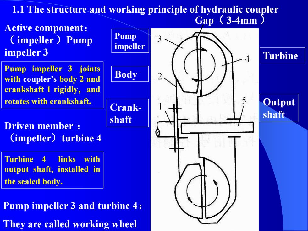
1.1 The structure and working principle of hydraulic coupler Gap (3-4mm Active component: impeller Pump Pump impeller impeller 3 Turbine Pump impeller 3 joints with coupler's body 2 and Body crankshaft 1 rigidly,and rotates with crankshaft. Crank- Output shaft shaft Driven member (impeller)turbine 4 Turbine 4 links with output shaft,installed in the sealed body. Pump impeller 3 and turbine 4: They are called working wheelCrankshaft Body Pump impeller Turbine Output shaft 1.1 The structure and working principle of hydraulic coupler Active component: ( impeller )Pump impeller 3 Driven member : (impeller)turbine 4 Pump impeller 3 joints with coupler’s body 2 and crankshaft 1 rigidly,and rotates with crankshaft. Turbine 4 links with output shaft, installed in the sealed body. Pump impeller 3 and turbine 4: They are called working wheel Gap( 3-4mm )