正在加载图片...
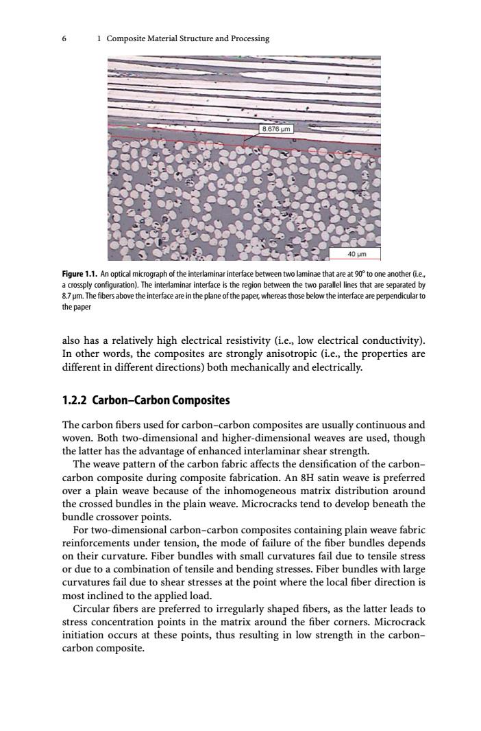
6 1 Composite Material Structure and Processing 8.676μm 40μm Figure 1.1.An optical micrograph of the interlaminar interface between two laminae that are at 90to one another(i.e, a crossply configuration).The interlaminar interface is the region between the two parallel lines that are separated by 8.7 um.The fibers above the interface are in the plane of the paper,whereas those below the interface are perpendicular to the paper also has a relatively high electrical resistivity (i.e.,low electrical conductivity). In other words,the composites are strongly anisotropic (i.e.,the properties are different in different directions)both mechanically and electrically. 1.2.2 Carbon-Carbon Composites The carbon fibers used for carbon-carbon composites are usually continuous and woven.Both two-dimensional and higher-dimensional weaves are used,though the latter has the advantage of enhanced interlaminar shear strength. The weave pattern of the carbon fabric affects the densification of the carbon- carbon composite during composite fabrication.An 8H satin weave is preferred over a plain weave because of the inhomogeneous matrix distribution around the crossed bundles in the plain weave.Microcracks tend to develop beneath the bundle crossover points. For two-dimensional carbon-carbon composites containing plain weave fabric reinforcements under tension,the mode of failure of the fiber bundles depends on their curvature.Fiber bundles with small curvatures fail due to tensile stress or due to a combination of tensile and bending stresses.Fiber bundles with large curvatures fail due to shear stresses at the point where the local fiber direction is most inclined to the applied load. Circular fibers are preferred to irregularly shaped fibers,as the latter leads to stress concentration points in the matrix around the fiber corners.Microcrack initiation occurs at these points,thus resulting in low strength in the carbon- carbon composite.6 1 Composite Material Structure and Processing Figure 1.1. An optical micrograph of the interlaminar interface between two laminae that are at 90° to one another (i.e., a crossply configuration). The interlaminar interface is the region between the two parallel lines that are separated by 8.7μm. The fibers above the interface are in the plane of the paper, whereas those below the interface are perpendicular to the paper also has a relatively high electrical resistivity (i.e., low electrical conductivity). In other words, the composites are strongly anisotropic (i.e., the properties are different in different directions) both mechanically and electrically. 1.2.2 Carbon–Carbon Composites The carbon fibers used for carbon–carbon composites are usually continuous and woven. Both two-dimensional and higher-dimensional weaves are used, though the latter has the advantage of enhanced interlaminar shear strength. The weave pattern of the carbon fabric affects the densification of the carbon– carbon composite during composite fabrication. An 8H satin weave is preferred over a plain weave because of the inhomogeneous matrix distribution around the crossed bundles in the plain weave. Microcracks tend to develop beneath the bundle crossover points. For two-dimensional carbon–carbon composites containing plain weave fabric reinforcements under tension, the mode of failure of the fiber bundles depends on their curvature. Fiber bundles with small curvatures fail due to tensile stress or due to a combination of tensile and bending stresses. Fiber bundles with large curvatures fail due to shear stresses at the point where the local fiber direction is most inclined to the applied load. Circular fibers are preferred to irregularly shaped fibers, as the latter leads to stress concentration points in the matrix around the fiber corners. Microcrack initiation occurs at these points, thus resulting in low strength in the carbon– carbon composite