正在加载图片...
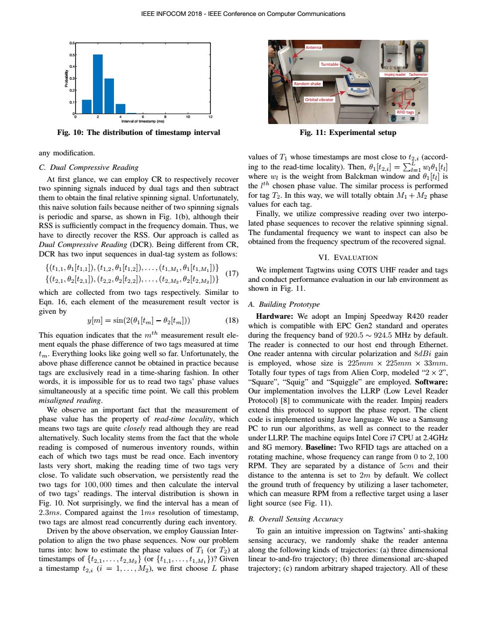
IEEE INFOCOM 2018-IEEE Conference on Computer Communications ntenna ndom shake Orbital vibrator 10 Interval of timestamp(ms) Fig.10:The distribution of timestamp interval Fig.11:Experimental setup any modification. values of T whose timestamps are most close to t2.i(accord- C.Dual Compressive Reading ing to the read-time locality).Then, At first glance,we can employ CR to respectively recover where wr is the weight from Balckman window and ti]is two spinning signals induced by dual tags and then subtract the lth chosen phase value.The similar process is performed them to obtain the final relative spinning signal.Unfortunately, for tag T2.In this way,we will totally obtain M+M2 phase this naive solution fails because neither of two spinning signals values for each tag. is periodic and sparse,as shown in Fig.1(b),although their Finally,we utilize compressive reading over two interpo- RSS is sufficiently compact in the frequency domain.Thus,we lated phase sequences to recover the relative spinning signal. have to directly recover the RSS.Our approach is called as The fundamental frequency we want to inspect can also be Dual Compressive Reading (DCR).Being different from CR, obtained from the frequency spectrum of the recovered signal. DCR has two input sequences in dual-tag system as follows: VI.EVALUATION {(t1,1,9[t1,]),(t,2,0t1,2]),,(t1,M1,01t1,M])} (17) We implement Tagtwins using COTS UHF reader and tags {(t2,1,2[t2,])(t2.2,2[t2,2l),(t2,M2,2[t2,M2]D} and conduct performance evaluation in our lab environment as which are collected from two tags respectively.Similar to shown in Fig.11. Egn.16,each element of the measurement result vector is A.Building Prototype given by ylm]sin(2(01[tm]-02[tm])) (18) Hardware:We adopt an Impinj Speedway R420 reader which is compatible with EPC Gen2 standard and operates This equation indicates that the mth measurement result ele- during the frequency band of 920.5~924.5 MHz by default. ment equals the phase difference of two tags measured at time The reader is connected to our host end through Ethernet. tm.Everything looks like going well so far.Unfortunately,the One reader antenna with circular polarization and 8dBi gain above phase difference cannot be obtained in practice because is employed,whose size is 225mm x 225mm x 33mm tags are exclusively read in a time-sharing fashion.In other Totally four types of tags from Alien Corp,modeled“2×2” words,it is impossible for us to read two tags'phase values “Square”,“Squig”and“Squiggle”are employed.Software: simultaneously at a specific time point.We call this problem Our implementation involves the LLRP (Low Level Reader misaligned reading. Protocol)[8]to communicate with the reader.Impinj readers We observe an important fact that the measurement of extend this protocol to support the phase report.The client phase value has the property of read-time locality,which code is implemented using Jave language.We use a Samsung means two tags are quite closely read although they are read PC to run our algorithms,as well as connect to the reader altematively.Such locality stems from the fact that the whole under LLRP.The machine equips Intel Core i7 CPU at 2.4GHz reading is composed of numerous inventory rounds,within and 8G memory.Baseline:Two RFID tags are attached on a each of which two tags must be read once.Each inventory rotating machine,whose frequency can range from 0 to 2,100 lasts very short,making the reading time of two tags very RPM.They are separated by a distance of 5cm and their close.To validate such observation,we persistently read the distance to the antenna is set to 2m by default.We collect two tags for 100,000 times and then calculate the interval the ground truth of frequency by utilizing a laser tachometer, of two tags'readings.The interval distribution is shown in which can measure RPM from a reflective target using a laser Fig.10.Not surprisingly,we find the interval has a mean of light source (see Fig.11). 2.3ms.Compared against the 1ms resolution of timestamp, two tags are almost read concurrently during each inventory. B.Overall Sensing Accuracy Driven by the above observation,we employ Gaussian Inter- To gain an intuitive impression on Tagtwins'anti-shaking polation to align the two phase sequences.Now our problem sensing accuracy,we randomly shake the reader antenna turns into:how to estimate the phase values of T(or T2)at along the following kinds of trajectories:(a)three dimensional timestamps of (2.1,...,t2.M (or {t1.1,...,M)?Given linear to-and-fro trajectory;(b)three dimensional arc-shaped a timestamp t2.i (i =1,...,M2),we first choose L phase trajectory;(c)random arbitrary shaped trajectory.All of these0 2 4 6 8 10 12 0 0.1 0.2 0.3 0.4 0.5 0.6 Interval of timestamp (ms) Probability Fig. 10: The distribution of timestamp interval any modification. C. Dual Compressive Reading At first glance, we can employ CR to respectively recover two spinning signals induced by dual tags and then subtract them to obtain the final relative spinning signal. Unfortunately, this naive solution fails because neither of two spinning signals is periodic and sparse, as shown in Fig. 1(b), although their RSS is sufficiently compact in the frequency domain. Thus, we have to directly recover the RSS. Our approach is called as Dual Compressive Reading (DCR). Being different from CR, DCR has two input sequences in dual-tag system as follows: {(t1,1, ✓1[t1,1]),(t1,2, ✓1[t1,2]),...,(t1,M1 , ✓1[t1,M1 ])} {(t2,1, ✓2[t2,1]),(t2,2, ✓2[t2,2]),...,(t2,M2 , ✓2[t2,M2 ])} (17) which are collected from two tags respectively. Similar to Eqn. 16, each element of the measurement result vector is given by y[m] = sin(2(✓1[tm] − ✓2[tm])) (18) This equation indicates that the mth measurement result element equals the phase difference of two tags measured at time tm. Everything looks like going well so far. Unfortunately, the above phase difference cannot be obtained in practice because tags are exclusively read in a time-sharing fashion. In other words, it is impossible for us to read two tags’ phase values simultaneously at a specific time point. We call this problem misaligned reading. We observe an important fact that the measurement of phase value has the property of read-time locality, which means two tags are quite closely read although they are read alternatively. Such locality stems from the fact that the whole reading is composed of numerous inventory rounds, within each of which two tags must be read once. Each inventory lasts very short, making the reading time of two tags very close. To validate such observation, we persistently read the two tags for 100, 000 times and then calculate the interval of two tags’ readings. The interval distribution is shown in Fig. 10. Not surprisingly, we find the interval has a mean of 2.3ms. Compared against the 1ms resolution of timestamp, two tags are almost read concurrently during each inventory. Driven by the above observation, we employ Gaussian Interpolation to align the two phase sequences. Now our problem turns into: how to estimate the phase values of T1 (or T2) at timestamps of {t2,1,...,t2,M2 } (or {t1,1,...,t1,M1 })? Given a timestamp t2,i (i = 1,...,M2), we first choose L phase Antenna Turntable Orbital vibrator RFID tags Impinj reader Tachometer Random shake Fig. 11: Experimental setup values of T1 whose timestamps are most close to t2,i (according to the read-time locality). Then, ✓1[t2,i] = PL l=1 wl✓1[tl] where wl is the weight from Balckman window and ✓1[tl] is the l th chosen phase value. The similar process is performed for tag T2. In this way, we will totally obtain M1 +M2 phase values for each tag. Finally, we utilize compressive reading over two interpolated phase sequences to recover the relative spinning signal. The fundamental frequency we want to inspect can also be obtained from the frequency spectrum of the recovered signal. VI. EVALUATION We implement Tagtwins using COTS UHF reader and tags and conduct performance evaluation in our lab environment as shown in Fig. 11. A. Building Prototype Hardware: We adopt an Impinj Speedway R420 reader which is compatible with EPC Gen2 standard and operates during the frequency band of 920.5 ⇠ 924.5 MHz by default. The reader is connected to our host end through Ethernet. One reader antenna with circular polarization and 8dBi gain is employed, whose size is 225mm ⇥ 225mm ⇥ 33mm. Totally four types of tags from Alien Corp, modeled “2 ⇥ 2”, “Square”, “Squig” and “Squiggle” are employed. Software: Our implementation involves the LLRP (Low Level Reader Protocol) [8] to communicate with the reader. Impinj readers extend this protocol to support the phase report. The client code is implemented using Jave language. We use a Samsung PC to run our algorithms, as well as connect to the reader under LLRP. The machine equips Intel Core i7 CPU at 2.4GHz and 8G memory. Baseline: Two RFID tags are attached on a rotating machine, whose frequency can range from 0 to 2, 100 RPM. They are separated by a distance of 5cm and their distance to the antenna is set to 2m by default. We collect the ground truth of frequency by utilizing a laser tachometer, which can measure RPM from a reflective target using a laser light source (see Fig. 11). B. Overall Sensing Accuracy To gain an intuitive impression on Tagtwins’ anti-shaking sensing accuracy, we randomly shake the reader antenna along the following kinds of trajectories: (a) three dimensional linear to-and-fro trajectory; (b) three dimensional arc-shaped trajectory; (c) random arbitrary shaped trajectory. All of these IEEE INFOCOM 2018 - IEEE Conference on Computer Communications