正在加载图片...
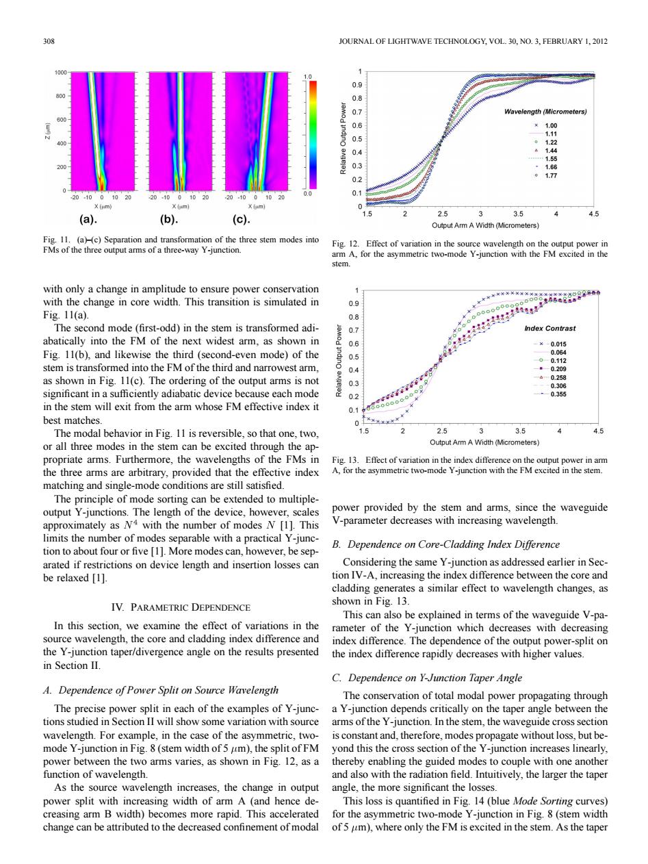
308 JOURNAL OF LIGHTWAVE TECHNOLOGY,VOL.30,NO.3,FEBRUARY 1,2012 0.9 NHU Wavelength (Micrometers) 0.6 ×1.00 0.5 -1.11 01.22 9 14 11.55 0.3 1.66 0 0.2 17 0.1 201000 X (um) X (um) X (um) 2.5 4 (a). (b) (c). 3.5 4.5 Output Arm A Width (Micrometers) Fig.11.(a)(c)Separation and transformation of the three stem modes into Fig.12.Effect of variation in the source wavelength on the output power in FMs of the three output arms of a three-way Y-junction. arm A,for the asymmetric two-mode Y-junction with the FM excited in the stem. with only a change in amplitude to ensure power conservation with the change in core width.This transition is simulated in 0.9 Fig.11(a). 0.8 The second mode (first-odd)in the stem is transformed adi- 0.7 Index Contrast abatically into the FM of the next widest arm,as shown in 06 北之一三三之字空“x -¥-0.015 Fig.11(b),and likewise the third(second-even mode)of the 0.5 0.064 -0-0.112 stem is transformed into the FM of the third and narrowest arm, 04 -—0.209 as shown in Fig.11(c).The ordering of the output arms is not -0.258 0.3 -0.306 significant in a sufficiently adiabatic device because each mode 0.2 -0.355 in the stem will exit from the arm whose FM effective index it 0.1 best matches. The modal behavior in Fig.11 is reversible,so that one,two, 1.5 2 2.5 3 3.5 4.5 or all three modes in the stem can be excited through the ap- Output Arm A Width (Micrometers) propriate arms.Furthermore,the wavelengths of the FMs in Fig.13.Effect of variation in the index difference on the output power in arm the three arms are arbitrary,provided that the effective index A,for the asymmetric two-mode Y-junction with the FM excited in the stem. matching and single-mode conditions are still satisfied. The principle of mode sorting can be extended to multiple- output Y-junctions.The length of the device,however,scales power provided by the stem and arms,since the waveguide approximately as N4 with the number of modes N [1].This V-parameter decreases with increasing wavelength. limits the number of modes separable with a practical Y-junc- B.Dependence on Core-Cladding Index Difference tion to about four or five [1].More modes can,however,be sep- arated if restrictions on device length and insertion losses can Considering the same Y-junction as addressed earlier in Sec- be relaxed [1]. tion IV-A,increasing the index difference between the core and cladding generates a similar effect to wavelength changes,as IV.PARAMETRIC DEPENDENCE shown in Fig.13. This can also be explained in terms of the waveguide V-pa- In this section,we examine the effect of variations in the rameter of the Y-junction which decreases with decreasing source wavelength,the core and cladding index difference and index difference.The dependence of the output power-split on the Y-junction taper/divergence angle on the results presented the index difference rapidly decreases with higher values. in Section II. C.Dependence on Y-Junction Taper Angle A.Dependence of Power Split on Source Wavelength The conservation of total modal power propagating through The precise power split in each of the examples of Y-junc- a Y-junction depends critically on the taper angle between the tions studied in Section II will show some variation with source arms of the Y-junction.In the stem,the waveguide cross section wavelength.For example,in the case of the asymmetric,two- is constant and,therefore,modes propagate without loss,but be- mode Y-junction in Fig.8(stem width of 5 um),the split of FM yond this the cross section of the Y-junction increases linearly, power between the two arms varies,as shown in Fig.12,as a thereby enabling the guided modes to couple with one another function of wavelength. and also with the radiation field.Intuitively,the larger the taper As the source wavelength increases,the change in output angle,the more significant the losses. power split with increasing width of arm A (and hence de- This loss is quantified in Fig.14(blue Mode Sorting curves) creasing arm B width)becomes more rapid.This accelerated for the asymmetric two-mode Y-junction in Fig.8(stem width change can be attributed to the decreased confinement of modal of 5 um),where only the FM is excited in the stem.As the taper308 JOURNAL OF LIGHTWAVE TECHNOLOGY, VOL. 30, NO. 3, FEBRUARY 1, 2012 Fig. 11. (a)–(c) Separation and transformation of the three stem modes into FMs of the three output arms of a three-way Y-junction. with only a change in amplitude to ensure power conservation with the change in core width. This transition is simulated in Fig. 11(a). The second mode (first-odd) in the stem is transformed adiabatically into the FM of the next widest arm, as shown in Fig. 11(b), and likewise the third (second-even mode) of the stem is transformed into the FM of the third and narrowest arm, as shown in Fig. 11(c). The ordering of the output arms is not significant in a sufficiently adiabatic device because each mode in the stem will exit from the arm whose FM effective index it best matches. The modal behavior in Fig. 11 is reversible, so that one, two, or all three modes in the stem can be excited through the appropriate arms. Furthermore, the wavelengths of the FMs in the three arms are arbitrary, provided that the effective index matching and single-mode conditions are still satisfied. The principle of mode sorting can be extended to multipleoutput Y-junctions. The length of the device, however, scales approximately as with the number of modes [1]. This limits the number of modes separable with a practical Y-junction to about four or five [1]. More modes can, however, be separated if restrictions on device length and insertion losses can be relaxed [1]. IV. PARAMETRIC DEPENDENCE In this section, we examine the effect of variations in the source wavelength, the core and cladding index difference and the Y-junction taper/divergence angle on the results presented in Section II. A. Dependence of Power Split on Source Wavelength The precise power split in each of the examples of Y-junctions studied in Section II will show some variation with source wavelength. For example, in the case of the asymmetric, twomode Y-junction in Fig. 8 (stem width of 5 m), the split of FM power between the two arms varies, as shown in Fig. 12, as a function of wavelength. As the source wavelength increases, the change in output power split with increasing width of arm A (and hence decreasing arm B width) becomes more rapid. This accelerated change can be attributed to the decreased confinement of modal Fig. 12. Effect of variation in the source wavelength on the output power in arm A, for the asymmetric two-mode Y-junction with the FM excited in the stem. Fig. 13. Effect of variation in the index difference on the output power in arm A, for the asymmetric two-mode Y-junction with the FM excited in the stem. power provided by the stem and arms, since the waveguide V-parameter decreases with increasing wavelength. B. Dependence on Core-Cladding Index Difference Considering the same Y-junction as addressed earlier in Section IV-A, increasing the index difference between the core and cladding generates a similar effect to wavelength changes, as shown in Fig. 13. This can also be explained in terms of the waveguide V-parameter of the Y-junction which decreases with decreasing index difference. The dependence of the output power-split on the index difference rapidly decreases with higher values. C. Dependence on Y-Junction Taper Angle The conservation of total modal power propagating through a Y-junction depends critically on the taper angle between the arms of the Y-junction. In the stem, the waveguide cross section is constant and, therefore, modes propagate without loss, but beyond this the cross section of the Y-junction increases linearly, thereby enabling the guided modes to couple with one another and also with the radiation field. Intuitively, the larger the taper angle, the more significant the losses. This loss is quantified in Fig. 14 (blue Mode Sorting curves) for the asymmetric two-mode Y-junction in Fig. 8 (stem width of 5 m), where only the FM is excited in the stem. As the taper