正在加载图片...
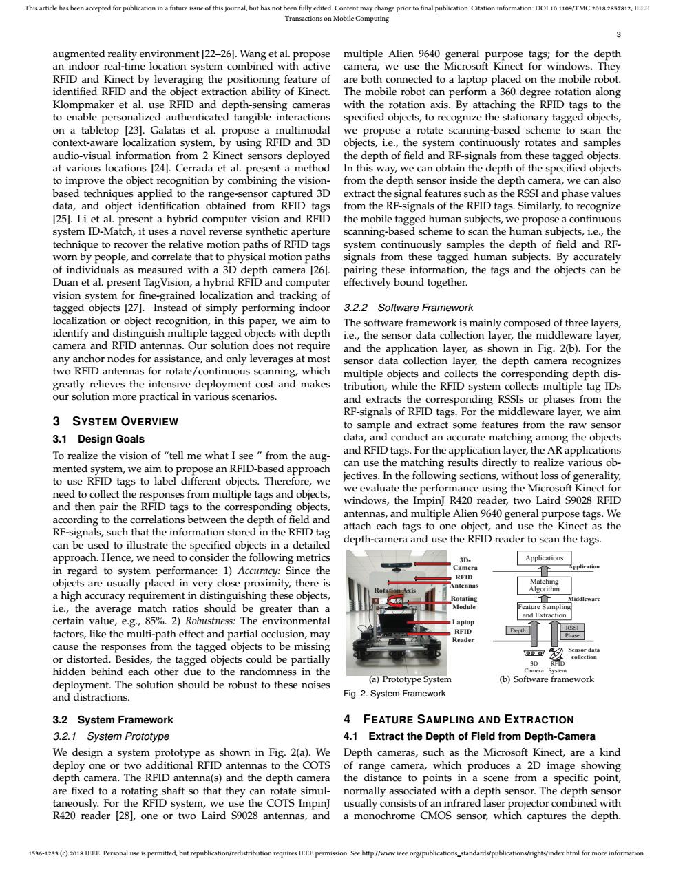
This article has been accepted for publication in a future issue of this journal,but has not been fully edited.Content may change prior to final publication.Citation information:DOI 10.1109/TMC.2018.2857812.IEEE Transactions on Mobile Computing 3 augmented reality environment [22-26].Wang et al.propose multiple Alien 9640 general purpose tags;for the depth an indoor real-time location system combined with active camera,we use the Microsoft Kinect for windows.They RFID and Kinect by leveraging the positioning feature of are both connected to a laptop placed on the mobile robot. identified RFID and the object extraction ability of Kinect. The mobile robot can perform a 360 degree rotation along Klompmaker et al.use RFID and depth-sensing cameras with the rotation axis.By attaching the RFID tags to the to enable personalized authenticated tangible interactions specified objects,to recognize the stationary tagged objects, on a tabletop [23].Galatas et al.propose a multimodal we propose a rotate scanning-based scheme to scan the context-aware localization system,by using RFID and 3D objects,i.e.,the system continuously rotates and samples audio-visual information from 2 Kinect sensors deployed the depth of field and RF-signals from these tagged objects. at various locations [24].Cerrada et al.present a method In this way,we can obtain the depth of the specified objects to improve the object recognition by combining the vision- from the depth sensor inside the depth camera,we can also based techniques applied to the range-sensor captured 3D extract the signal features such as the RSSI and phase values data,and object identification obtained from RFID tags from the RF-signals of the RFID tags.Similarly,to recognize [25].Li et al.present a hybrid computer vision and RFID the mobile tagged human subjects,we propose a continuous system ID-Match,it uses a novel reverse synthetic aperture scanning-based scheme to scan the human subjects,i.e.,the technique to recover the relative motion paths of RFID tags system continuously samples the depth of field and RF- worn by people,and correlate that to physical motion paths signals from these tagged human subjects.By accurately of individuals as measured with a 3D depth camera [26]. pairing these information,the tags and the objects can be Duan et al.present TagVision,a hybrid RFID and computer effectively bound together. vision system for fine-grained localization and tracking of tagged objects [27].Instead of simply performing indoor 3.2.2 Software Framework localization or object recognition,in this paper,we aim to The software framework is mainly composed of three layers, identify and distinguish multiple tagged objects with depth i.e.,the sensor data collection layer,the middleware layer, camera and RFID antennas.Our solution does not require and the application layer,as shown in Fig.2(b).For the any anchor nodes for assistance,and only leverages at most sensor data collection layer,the depth camera recognizes two RFID antennas for rotate/continuous scanning,which multiple objects and collects the corresponding depth dis- greatly relieves the intensive deployment cost and makes tribution,while the RFID system collects multiple tag IDs our solution more practical in various scenarios. and extracts the corresponding RSSIs or phases from the RF-signals of RFID tags.For the middleware layer,we aim SYSTEM OVERVIEW to sample and extract some features from the raw sensor 3.1 Design Goals data,and conduct an accurate matching among the objects To realize the vision of "tell me what I see from the aug- and RFID tags.For the application layer,the AR applications mented system,we aim to propose an RFID-based approach can use the matching results directly to realize various ob- to use RFID tags to label different objects.Therefore,we jectives.In the following sections,without loss of generality, need to collect the responses from multiple tags and objects, we evaluate the performance using the Microsoft Kinect for and then pair the RFID tags to the corresponding objects, windows,the ImpinJ R420 reader,two Laird S9028 RFID according to the correlations between the depth of field and antennas,and multiple Alien 9640 general purpose tags.We RF-signals,such that the information stored in the RFID tag attach each tags to one object,and use the Kinect as the can be used to illustrate the specified objects in a detailed depth-camera and use the RFID reader to scan the tags. approach.Hence,we need to consider the following metrics 3D. Applications in regard to system performance:1)Accuracy:Since the Camera RFID objects are usually placed in very close proximity,there is Matching ntennas Algorithm a high accuracy requirement in distinguishing these objects, Rotating 1 i.e.,the average match ratios should be greater than a Module Feature Sampling and Extraction certain value,e.g.,85%.2)Robustness:The environmental Laptop factors,like the multi-path effect and partial occlusion,may RFID Reader cause the responses from the tagged objects to be missing or distorted.Besides,the tagged objects could be partially 3D hidden behind each other due to the randomness in the deployment.The solution should be robust to these noises (a)Prototype System (b)Software framework and distractions Fig.2.System Framework 3.2 System Framework 4 FEATURE SAMPLING AND EXTRACTION 3.2.1 System Prototype 4.1 Extract the Depth of Field from Depth-Camera We design a system prototype as shown in Fig.2(a).We Depth cameras,such as the Microsoft Kinect,are a kind deploy one or two additional RFID antennas to the COTS of range camera,which produces a 2D image showing depth camera.The RFID antenna(s)and the depth camera the distance to points in a scene from a specific point, are fixed to a rotating shaft so that they can rotate simul- normally associated with a depth sensor.The depth sensor taneously.For the RFID system,we use the COTS Impin] usually consists of an infrared laser projector combined with R420 reader [28],one or two Laird S9028 antennas,and a monochrome CMOS sensor,which captures the depth. 1536-1233(c)2018 IEEE Personal use is permitted,but republication/redistribution requires IEEE permission.See http://www.ieee.org/publications_standards/publications/rights/index.html for more information.1536-1233 (c) 2018 IEEE. Personal use is permitted, but republication/redistribution requires IEEE permission. See http://www.ieee.org/publications_standards/publications/rights/index.html for more information. This article has been accepted for publication in a future issue of this journal, but has not been fully edited. Content may change prior to final publication. Citation information: DOI 10.1109/TMC.2018.2857812, IEEE Transactions on Mobile Computing 3 augmented reality environment [22–26]. Wang et al. propose an indoor real-time location system combined with active RFID and Kinect by leveraging the positioning feature of identified RFID and the object extraction ability of Kinect. Klompmaker et al. use RFID and depth-sensing cameras to enable personalized authenticated tangible interactions on a tabletop [23]. Galatas et al. propose a multimodal context-aware localization system, by using RFID and 3D audio-visual information from 2 Kinect sensors deployed at various locations [24]. Cerrada et al. present a method to improve the object recognition by combining the visionbased techniques applied to the range-sensor captured 3D data, and object identification obtained from RFID tags [25]. Li et al. present a hybrid computer vision and RFID system ID-Match, it uses a novel reverse synthetic aperture technique to recover the relative motion paths of RFID tags worn by people, and correlate that to physical motion paths of individuals as measured with a 3D depth camera [26]. Duan et al. present TagVision, a hybrid RFID and computer vision system for fine-grained localization and tracking of tagged objects [27]. Instead of simply performing indoor localization or object recognition, in this paper, we aim to identify and distinguish multiple tagged objects with depth camera and RFID antennas. Our solution does not require any anchor nodes for assistance, and only leverages at most two RFID antennas for rotate/continuous scanning, which greatly relieves the intensive deployment cost and makes our solution more practical in various scenarios. 3 SYSTEM OVERVIEW 3.1 Design Goals To realize the vision of “tell me what I see ” from the augmented system, we aim to propose an RFID-based approach to use RFID tags to label different objects. Therefore, we need to collect the responses from multiple tags and objects, and then pair the RFID tags to the corresponding objects, according to the correlations between the depth of field and RF-signals, such that the information stored in the RFID tag can be used to illustrate the specified objects in a detailed approach. Hence, we need to consider the following metrics in regard to system performance: 1) Accuracy: Since the objects are usually placed in very close proximity, there is a high accuracy requirement in distinguishing these objects, i.e., the average match ratios should be greater than a certain value, e.g., 85%. 2) Robustness: The environmental factors, like the multi-path effect and partial occlusion, may cause the responses from the tagged objects to be missing or distorted. Besides, the tagged objects could be partially hidden behind each other due to the randomness in the deployment. The solution should be robust to these noises and distractions. 3.2 System Framework 3.2.1 System Prototype We design a system prototype as shown in Fig. 2(a). We deploy one or two additional RFID antennas to the COTS depth camera. The RFID antenna(s) and the depth camera are fixed to a rotating shaft so that they can rotate simultaneously. For the RFID system, we use the COTS ImpinJ R420 reader [28], one or two Laird S9028 antennas, and multiple Alien 9640 general purpose tags; for the depth camera, we use the Microsoft Kinect for windows. They are both connected to a laptop placed on the mobile robot. The mobile robot can perform a 360 degree rotation along with the rotation axis. By attaching the RFID tags to the specified objects, to recognize the stationary tagged objects, we propose a rotate scanning-based scheme to scan the objects, i.e., the system continuously rotates and samples the depth of field and RF-signals from these tagged objects. In this way, we can obtain the depth of the specified objects from the depth sensor inside the depth camera, we can also extract the signal features such as the RSSI and phase values from the RF-signals of the RFID tags. Similarly, to recognize the mobile tagged human subjects, we propose a continuous scanning-based scheme to scan the human subjects, i.e., the system continuously samples the depth of field and RFsignals from these tagged human subjects. By accurately pairing these information, the tags and the objects can be effectively bound together. 3.2.2 Software Framework The software framework is mainly composed of three layers, i.e., the sensor data collection layer, the middleware layer, and the application layer, as shown in Fig. 2(b). For the sensor data collection layer, the depth camera recognizes multiple objects and collects the corresponding depth distribution, while the RFID system collects multiple tag IDs and extracts the corresponding RSSIs or phases from the RF-signals of RFID tags. For the middleware layer, we aim to sample and extract some features from the raw sensor data, and conduct an accurate matching among the objects and RFID tags. For the application layer, the AR applications can use the matching results directly to realize various objectives. In the following sections, without loss of generality, we evaluate the performance using the Microsoft Kinect for windows, the ImpinJ R420 reader, two Laird S9028 RFID antennas, and multiple Alien 9640 general purpose tags. We attach each tags to one object, and use the Kinect as the depth-camera and use the RFID reader to scan the tags. 3DCamera RFID Antennas Rotating Module RFID Reader Laptop Rotation Axis (a) Prototype System Applications Application Matching Algorithm Feature Sampling and Extraction Middleware Depth 3D Camera RFID System RSSI Phase Sensor data collection (b) Software framework Fig. 2. System Framework 4 FEATURE SAMPLING AND EXTRACTION 4.1 Extract the Depth of Field from Depth-Camera Depth cameras, such as the Microsoft Kinect, are a kind of range camera, which produces a 2D image showing the distance to points in a scene from a specific point, normally associated with a depth sensor. The depth sensor usually consists of an infrared laser projector combined with a monochrome CMOS sensor, which captures the depth