正在加载图片...
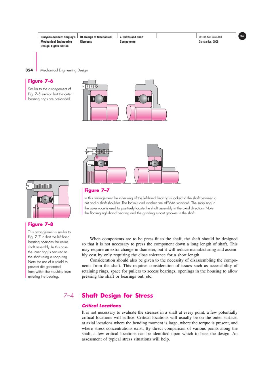
Budynas-Nisbett:Shigley's Ill.Design of Mechanical 7.Shafts and Shaft ©The McGra-Hfl 357 Mechanical Engineering Elements Components Companies,2008 Design,Eighth Edition 354 Mechanical Engineering Design Figure 7-6 Similar to the arrangement of Fig.7-5 except that the outer bearing rings are preloaded. 咖I0 Figure 7-7 In this arrangement the inner ring of the lefthand bearing is locked to the shaft between a nut and a shaft shoulder.The locknut and washer are AFBMA standard.The snap ring in the outer race is used to positively locate the shaft assembly in the axial direction.Note the floating righthand bearing and the grinding runout grooves in the shaft. Figure 7-8 This arrangement is similar to Fig.7-7 in that the left-hand When components are to be press-fit to the shaft,the shaft should be designed bearing positions the entire so that it is not necessary to press the component down a long length of shaft.This shaft assembly.In this case the inner ring is secured to may require an extra change in diameter,but it will reduce manufacturing and assem- the shaft using a snap ring. bly cost by only requiring the close tolerance for a short length. Note the use of a shield to Consideration should also be given to the necessity of disassembling the compo- prevent dirt generated nents from the shaft.This requires consideration of issues such as accessibility of from within the machine from retaining rings,space for pullers to access bearings.openings in the housing to allow entering the bearing. pressing the shaft or bearings out,etc. 7-4 Shaft Design for Stress Critical Locations It is not necessary to evaluate the stresses in a shaft at every point;a few potentially critical locations will suffice.Critical locations will usually be on the outer surface. at axial locations where the bending moment is large,where the torque is present,and where stress concentrations exist.By direct comparison of various points along the shaft,a few critical locations can be identified upon which to base the design.An assessment of typical stress situations will help.Budynas−Nisbett: Shigley’s Mechanical Engineering Design, Eighth Edition III. Design of Mechanical Elements 7. Shafts and Shaft Components © The McGraw−Hill 357 Companies, 2008 354 Mechanical Engineering Design Figure 7–6 Similar to the arrangement of Fig. 7--5 except that the outer bearing rings are preloaded. Figure 7–7 In this arrangement the inner ring of the left-hand bearing is locked to the shaft between a nut and a shaft shoulder. The locknut and washer are AFBMA standard. The snap ring in the outer race is used to positively locate the shaft assembly in the axial direction. Note the floating right-hand bearing and the grinding runout grooves in the shaft. When components are to be press-fit to the shaft, the shaft should be designed so that it is not necessary to press the component down a long length of shaft. This may require an extra change in diameter, but it will reduce manufacturing and assembly cost by only requiring the close tolerance for a short length. Consideration should also be given to the necessity of disassembling the components from the shaft. This requires consideration of issues such as accessibility of retaining rings, space for pullers to access bearings, openings in the housing to allow pressing the shaft or bearings out, etc. 7–4 Shaft Design for Stress Critical Locations It is not necessary to evaluate the stresses in a shaft at every point; a few potentially critical locations will suffice. Critical locations will usually be on the outer surface, at axial locations where the bending moment is large, where the torque is present, and where stress concentrations exist. By direct comparison of various points along the shaft, a few critical locations can be identified upon which to base the design. An assessment of typical stress situations will help. Figure 7–8 This arrangement is similar to Fig. 7--7 in that the left-hand bearing positions the entire shaft assembly. In this case the inner ring is secured to the shaft using a snap ring. Note the use of a shield to prevent dirt generated from within the machine from entering the bearing