正在加载图片...
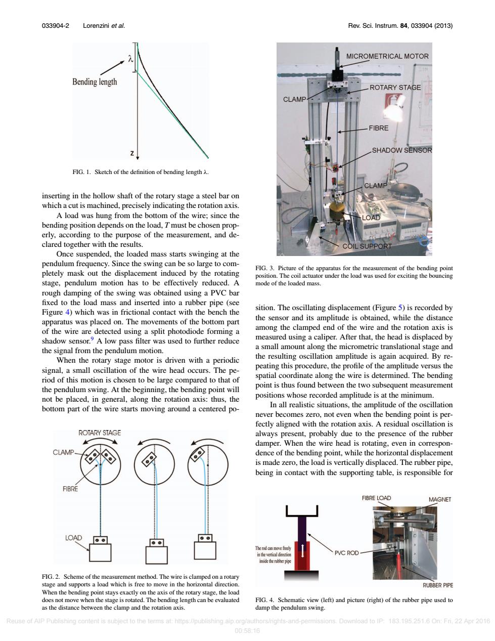
033904-2 Lorenzini et al. Rev.Sci.Instrum.84,033904(2013) MICROMETRICAL MOTOR Bending length ROTARY STAGE CLAMP FIBRE SHADOW SENSOR FIG.1.Sketch of the definition of bending length A. inserting in the hollow shaft of the rotary stage a steel bar on which a cut is machined,precisely indicating the rotation axis. A load was hung from the bottom of the wire;since the bending position depends on the load,T must be chosen prop- erly,according to the purpose of the measurement,and de- clared together with the results. COIL SUPPORT Once suspended,the loaded mass starts swinging at the pendulum frequency.Since the swing can be so large to com- FIG.3.Picture of the apparatus for the measurement of the bending point pletely mask out the displacement induced by the rotating position.The coil actuator under the load was used for exciting the bouncing stage,pendulum motion has to be effectively reduced.A mode of the loaded mass. rough damping of the swing was obtained using a PVC bar fixed to the load mass and inserted into a rubber pipe(see sition.The oscillating displacement(Figure 5)is recorded by Figure 4)which was in frictional contact with the bench the apparatus was placed on.The movements of the bottom part the sensor and its amplitude is obtained,while the distance of the wire are detected using a split photodiode forming a among the clamped end of the wire and the rotation axis is shadow sensor.A low pass filter was used to further reduce measured using a caliper.After that,the head is displaced by the signal from the pendulum motion. a small amount along the micrometric translational stage and When the rotary stage motor is driven with a periodic the resulting oscillation amplitude is again acquired.By re- signal,a small oscillation of the wire head occurs.The pe- peating this procedure,the profile of the amplitude versus the riod of this motion is chosen to be large compared to that of spatial coordinate along the wire is determined.The bending the pendulum swing.At the beginning,the bending point will point is thus found between the two subsequent measurement not be placed,in general,along the rotation axis:thus,the positions whose recorded amplitude is at the minimum. bottom part of the wire starts moving around a centered po- In all realistic situations,the amplitude of the oscillation never becomes zero,not even when the bending point is per- fectly aligned with the rotation axis.A residual oscillation is ROTARY STAGE always present,probably due to the presence of the rubber damper.When the wire head is rotating,even in correspon- CLAMP dence of the bending point,while the horizontal displacement is made zero,the load is vertically displaced.The rubber pipe, being in contact with the supporting table,is responsible for FIBRE FIBRE LOAD MAGNET LOAD eertealretio C ROD side he FIG.2.Scheme of the measurement method.The wire is clamped on a rotary stage and supports a load which is free to move in the horizontal direction. RUBBER PIPE When the bending point stays exactly on the axis of the rotary stage,the load does not move when the stage is rotated.The bending length can be evaluated FIG.4.Schematic view (left)and picture (right)of the rubber pipe used to as the distance between the clamp and the rotation axis. damp the pendulum swing. Reuse of AlP Publishing content is subject to the terms at:https://publishing.aip.org/authors/rights-and-permissions.Download to IP:183.195.251.6 On:Fri.22 Apr 2016 00:58:16033904-2 Lorenzini et al. Rev. Sci. Instrum. 84, 033904 (2013) FIG. 1. Sketch of the definition of bending length λ. inserting in the hollow shaft of the rotary stage a steel bar on which a cut is machined, precisely indicating the rotation axis. A load was hung from the bottom of the wire; since the bending position depends on the load, T must be chosen properly, according to the purpose of the measurement, and declared together with the results. Once suspended, the loaded mass starts swinging at the pendulum frequency. Since the swing can be so large to completely mask out the displacement induced by the rotating stage, pendulum motion has to be effectively reduced. A rough damping of the swing was obtained using a PVC bar fixed to the load mass and inserted into a rubber pipe (see Figure 4) which was in frictional contact with the bench the apparatus was placed on. The movements of the bottom part of the wire are detected using a split photodiode forming a shadow sensor.9 A low pass filter was used to further reduce the signal from the pendulum motion. When the rotary stage motor is driven with a periodic signal, a small oscillation of the wire head occurs. The period of this motion is chosen to be large compared to that of the pendulum swing. At the beginning, the bending point will not be placed, in general, along the rotation axis: thus, the bottom part of the wire starts moving around a centered poFIG. 2. Scheme of the measurement method. The wire is clamped on a rotary stage and supports a load which is free to move in the horizontal direction. When the bending point stays exactly on the axis of the rotary stage, the load does not move when the stage is rotated. The bending length can be evaluated as the distance between the clamp and the rotation axis. FIG. 3. Picture of the apparatus for the measurement of the bending point position. The coil actuator under the load was used for exciting the bouncing mode of the loaded mass. sition. The oscillating displacement (Figure 5) is recorded by the sensor and its amplitude is obtained, while the distance among the clamped end of the wire and the rotation axis is measured using a caliper. After that, the head is displaced by a small amount along the micrometric translational stage and the resulting oscillation amplitude is again acquired. By repeating this procedure, the profile of the amplitude versus the spatial coordinate along the wire is determined. The bending point is thus found between the two subsequent measurement positions whose recorded amplitude is at the minimum. In all realistic situations, the amplitude of the oscillation never becomes zero, not even when the bending point is perfectly aligned with the rotation axis. A residual oscillation is always present, probably due to the presence of the rubber damper. When the wire head is rotating, even in correspondence of the bending point, while the horizontal displacement is made zero, the load is vertically displaced. The rubber pipe, being in contact with the supporting table, is responsible for FIG. 4. Schematic view (left) and picture (right) of the rubber pipe used to damp the pendulum swing. Reuse of AIP Publishing content is subject to the terms at: https://publishing.aip.org/authors/rights-and-permissions. Download to IP: 183.195.251.6 On: Fri, 22 Apr 2016 00:58:16