正在加载图片...

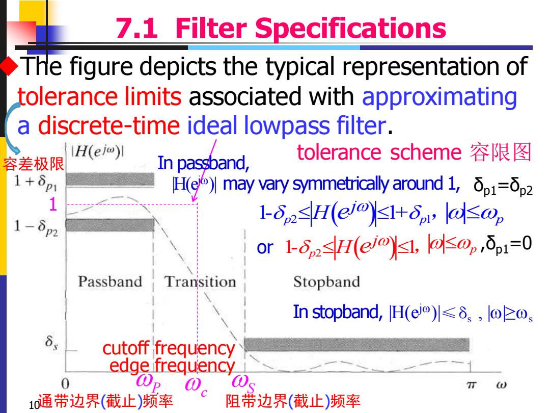
7.1 Filter Specifications THe figure depicts the typical representation of tolerance limits associated with approximating a discrete-time ideal lowpass filter. H(ej)l 容差极限 In passband, tolerance scheme容限图 1+δp H(may vary symmetrically around1,δp1=δp2 1 1-823H(elo)3Hp,laop 1- or1-ozH(e/lls0δ1=0 Passband Transition Stopband In stopband,H(eo)l≤δs,wzo cutoff frequency edge frequency 0 T 10通带边界(截止)频率 阻带边界(截止)频率10 7.1 Filter Specifications tolerance scheme 容限图 ◆The figure depicts the typical representation of tolerance limits associated with approximating a discrete-time ideal lowpass filter. edge frequency |H(e j)| may vary symmetrically around 1, δp1=δp2 or ,δp1=0 cutoff frequency 1 c 容差极限 通带边界(截止)频率 阻带边界(截止)频率 P S 1- 1 p2 ( ) H j e , p 1- 1+ p p 2 1 ( ) H j e , p In passband, In stopband, |H(e j)|≤δs , ||≥s