正在加载图片...
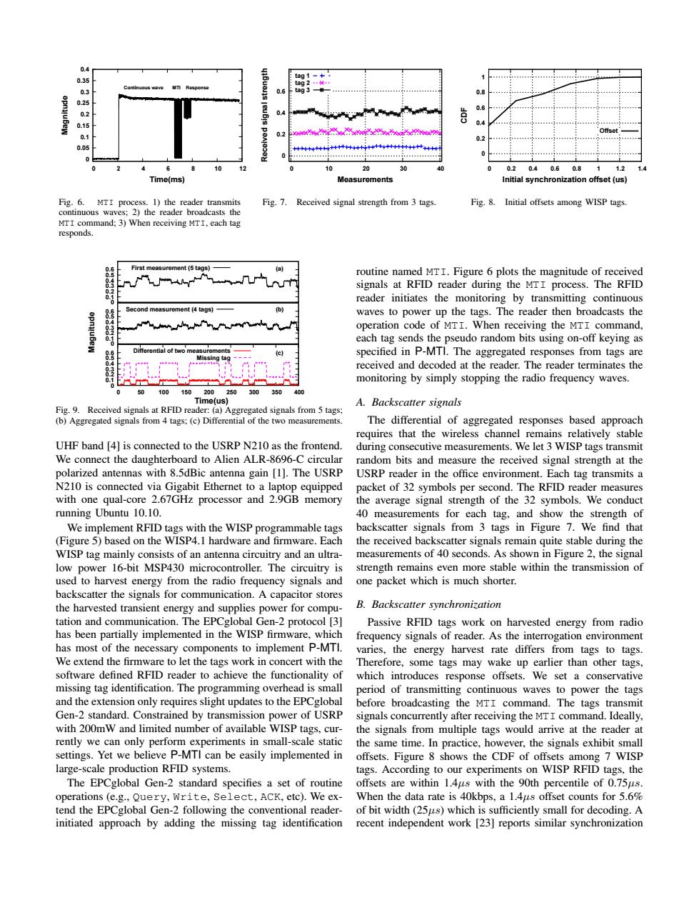
0.4 0.35 tag1-+ 8g2" 3 ag 3- 0.8 0.6 0.2 0 0.15 0.1 0.2 0.2 0.05 +++4+++++++ 4+4++ 0 10 20 30 40 0 0.2 0.4 0.6 0.8 1 12 Time(ms) Measurements Initial synchronization offset(us) F5g.6. MTI process.1)the reader transmits Fig.7. Received signal strength from 3 tags. Fig.8.Initial offsets among WISP tags. continuous waves:2)the reader broadcasts the MTI command;3)When receiving MTI,each tag responds. First measurement(5 tags) a routine named MTI.Figure 6 plots the magnitude of received signals at RFID reader during the MTI process.The RFID reader initiates the monitoring by transmitting continuous Second measurement (4 tags) waves to power up the tags.The reader then broadcasts the operation code of MTI.When receiving the MTI command, each tag sends the pseudo random bits using on-off keying as Differential of two measurement specified in P-MTI.The aggregated responses from tags are received and decoded at the reader.The reader terminates the monitoring by simply stopping the radio frequency waves. 0 50 100150200250300 350 400 Time(us) A.Backscatter signals Fig.9.Received signals at RFID reader:(a)Aggregated signals from 5 tags; (b)Aggregated signals from 4 tags:(c)Differential of the two measurements. The differential of aggregated responses based approach requires that the wireless channel remains relatively stable UHF band [4]is connected to the USRP N210 as the frontend. during consecutive measurements.We let 3 WISP tags transmit We connect the daughterboard to Alien ALR-8696-C circular random bits and measure the received signal strength at the polarized antennas with 8.5dBic antenna gain [1].The USRP USRP reader in the office environment.Each tag transmits a N210 is connected via Gigabit Ethernet to a laptop equipped packet of 32 symbols per second.The RFID reader measures with one qual-core 2.67GHz processor and 2.9GB memory the average signal strength of the 32 symbols.We conduct running Ubuntu 10.10. 40 measurements for each tag,and show the strength of We implement RFID tags with the WISP programmable tags backscatter signals from 3 tags in Figure 7.We find that (Figure 5)based on the WISP4.1 hardware and firmware.Each the received backscatter signals remain quite stable during the WISP tag mainly consists of an antenna circuitry and an ultra- measurements of 40 seconds.As shown in Figure 2,the signal low power 16-bit MSP430 microcontroller.The circuitry is strength remains even more stable within the transmission of used to harvest energy from the radio frequency signals and one packet which is much shorter. backscatter the signals for communication.A capacitor stores the harvested transient energy and supplies power for compu- B.Backscatter synchronization tation and communication.The EPCglobal Gen-2 protocol [3] Passive RFID tags work on harvested energy from radio has been partially implemented in the WISP firmware,which frequency signals of reader.As the interrogation environment has most of the necessary components to implement P-MTI. varies,the energy harvest rate differs from tags to tags. We extend the firmware to let the tags work in concert with the Therefore,some tags may wake up earlier than other tags, software defined RFID reader to achieve the functionality of which introduces response offsets.We set a conservative missing tag identification.The programming overhead is small period of transmitting continuous waves to power the tags and the extension only requires slight updates to the EPCglobal before broadcasting the MTI command.The tags transmit Gen-2 standard.Constrained by transmission power of USRP signals concurrently after receiving the MTI command.Ideally, with 200mW and limited number of available WISP tags,cur- the signals from multiple tags would arrive at the reader at rently we can only perform experiments in small-scale static the same time.In practice,however,the signals exhibit small settings.Yet we believe P-MTI can be easily implemented in offsets.Figure 8 shows the CDF of offsets among 7WISP large-scale production RFID systems. tags.According to our experiments on WISP RFID tags,the The EPCglobal Gen-2 standard specifies a set of routine offsets are within 1.4us with the 90th percentile of 0.75us. operations (e.g.,Query,Write,Select,ACK,etc).We ex-When the data rate is 40kbps,a 1.4us offset counts for 5.6% tend the EPCglobal Gen-2 following the conventional reader- of bit width(25us)which is sufficiently small for decoding.A initiated approach by adding the missing tag identification recent independent work [23]reports similar synchronization0 0.05 0.1 0.15 0.2 0.25 0.3 0.35 0.4 0 2 4 6 8 10 12 Magnitude Time(ms) Continuous wave MTI Response Fig. 6. MTI process. 1) the reader transmits continuous waves; 2) the reader broadcasts the MTI command; 3) When receiving MTI, each tag responds. 0 0.2 0.4 0.6 0 10 20 30 40 Received signal strength Measurements tag 1 tag 2 tag 3 Fig. 7. Received signal strength from 3 tags. 0 0.2 0.4 0.6 0.8 1 0 0.2 0.4 0.6 0.8 1 1.2 1.4 CDF Initial synchronization offset (us) Offset Fig. 8. Initial offsets among WISP tags. 0 0.1 0.2 0.3 0.4 0.5 0.6 First measurement (5 tags) 0 0.1 0.2 0.3 0.4 0.5 0.6 Second measurement (4 tags) 0 0.1 0.2 0.3 0.4 0.5 0.6 0 50 100 150 200 250 300 350 400 (a) (b) (c) Time(us) Magnitude Differential of two measurements Missing tag Fig. 9. Received signals at RFID reader: (a) Aggregated signals from 5 tags; (b) Aggregated signals from 4 tags; (c) Differential of the two measurements. UHF band [4] is connected to the USRP N210 as the frontend. We connect the daughterboard to Alien ALR-8696-C circular polarized antennas with 8.5dBic antenna gain [1]. The USRP N210 is connected via Gigabit Ethernet to a laptop equipped with one qual-core 2.67GHz processor and 2.9GB memory running Ubuntu 10.10. We implement RFID tags with the WISP programmable tags (Figure 5) based on the WISP4.1 hardware and firmware. Each WISP tag mainly consists of an antenna circuitry and an ultralow power 16-bit MSP430 microcontroller. The circuitry is used to harvest energy from the radio frequency signals and backscatter the signals for communication. A capacitor stores the harvested transient energy and supplies power for computation and communication. The EPCglobal Gen-2 protocol [3] has been partially implemented in the WISP firmware, which has most of the necessary components to implement P-MTI. We extend the firmware to let the tags work in concert with the software defined RFID reader to achieve the functionality of missing tag identification. The programming overhead is small and the extension only requires slight updates to the EPCglobal Gen-2 standard. Constrained by transmission power of USRP with 200mW and limited number of available WISP tags, currently we can only perform experiments in small-scale static settings. Yet we believe P-MTI can be easily implemented in large-scale production RFID systems. The EPCglobal Gen-2 standard specifies a set of routine operations (e.g., Query, Write, Select, ACK, etc). We extend the EPCglobal Gen-2 following the conventional readerinitiated approach by adding the missing tag identification routine named MTI. Figure 6 plots the magnitude of received signals at RFID reader during the MTI process. The RFID reader initiates the monitoring by transmitting continuous waves to power up the tags. The reader then broadcasts the operation code of MTI. When receiving the MTI command, each tag sends the pseudo random bits using on-off keying as specified in P-MTI. The aggregated responses from tags are received and decoded at the reader. The reader terminates the monitoring by simply stopping the radio frequency waves. A. Backscatter signals The differential of aggregated responses based approach requires that the wireless channel remains relatively stable during consecutive measurements. We let 3 WISP tags transmit random bits and measure the received signal strength at the USRP reader in the office environment. Each tag transmits a packet of 32 symbols per second. The RFID reader measures the average signal strength of the 32 symbols. We conduct 40 measurements for each tag, and show the strength of backscatter signals from 3 tags in Figure 7. We find that the received backscatter signals remain quite stable during the measurements of 40 seconds. As shown in Figure 2, the signal strength remains even more stable within the transmission of one packet which is much shorter. B. Backscatter synchronization Passive RFID tags work on harvested energy from radio frequency signals of reader. As the interrogation environment varies, the energy harvest rate differs from tags to tags. Therefore, some tags may wake up earlier than other tags, which introduces response offsets. We set a conservative period of transmitting continuous waves to power the tags before broadcasting the MTI command. The tags transmit signals concurrently after receiving the MTI command. Ideally, the signals from multiple tags would arrive at the reader at the same time. In practice, however, the signals exhibit small offsets. Figure 8 shows the CDF of offsets among 7 WISP tags. According to our experiments on WISP RFID tags, the offsets are within 1.4µs with the 90th percentile of 0.75µs. When the data rate is 40kbps, a 1.4µs offset counts for 5.6% of bit width (25µs) which is sufficiently small for decoding. A recent independent work [23] reports similar synchronization