正在加载图片...
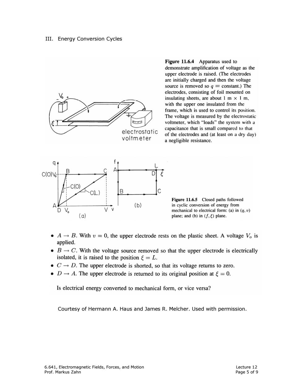
III.Energy Conversion Cycles Figure 11.6.4 Apparatus used to demonstrate amplification of voltage as the upper electrode is raised.(The electrodes are initially charged and then the voltage source is removed so g constant.)The electrodes,consisting of foil mounted on insulating sheets,are about 1 m x I m. with the upper one insulated from the frame,which is used to control its position. The voltage is measured by the electrostatic voltmeter,which“loads'”the system with a electrostatic capacitance that is small compared to that of the electrodes and (at least on a dry day) voltmeter a negligible resistance. B C(OV -C(O) C(L) B Figure 11.6.5 Closed paths followed A (b) in cyclic conversion of energy from DV mechanical to electrical form:(a)in(q,v) (a) plane;and (b)in (f,)plane. .A-B.With v=0,the upper electrode rests on the plastic sheet.A voltage Vo is applied. B-C.With the voltage source removed so that the upper electrode is electrically isolated,it is raised to the position =L. .C-D.The upper electrode is shorted,so that its voltage returns to zero. ·D→A.The upper electrode is retured to its original position atξ=O. Is electrical energy converted to mechanical form,or vice versa? Courtesy of Hermann A.Haus and James R.Melcher.Used with permission. 6.641,Electromagnetic Fields,Forces,and Motion Lecture 12 Prof.Markus Zahn Page 5 of 96.641, Electromagnetic Fields, Forces, and Motion Lecture 12 Prof. Markus Zahn Page 5 of 9 III. Energy Conversion Cycles Courtesy of Hermann A. Haus and James R. Melcher. Used with permission