正在加载图片...
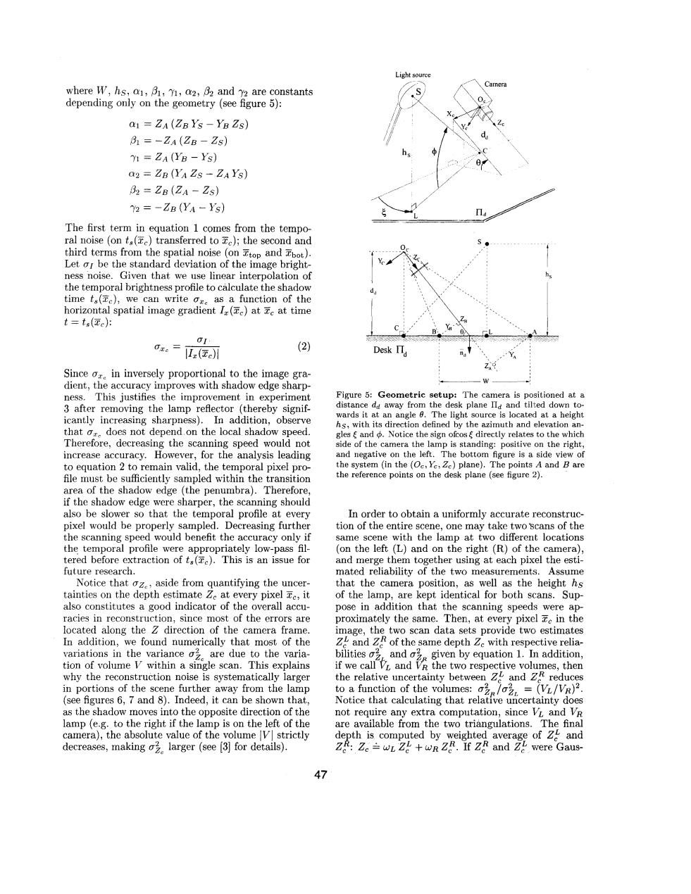
Light source where W,hs,a1,B1,1,a2,B2 and 72 are constants depending only on the geometry(see figure 5): a1=ZA(ZBYs-YBZs) B1=-ZA(ZB-Zs) 71=ZA(YB-Ys) Q2 ZB(YA Zs-ZA Ys) 82=ZB(ZA-Zs) Y2 =-ZB (YA-Ys) The first term in equation 1 comes from the tempo- ral noise (on t(e)transferred to c);the second and third terms from the spatial noise (on Ttop and Tbot). Let o be the standard deviation of the image bright- ness noise.Given that we use linear interpolation of the temporal brightness profile to calculate the shadow time ta(e),we can write o as a function of the horizontal spatial image gradient I(c)at Te at time t=ts(Te): Oxe=Iz(c) (2) Desk I Since or in inversely proportional to the image gra- dient,the accuracy improves with shadow edge sharp- ness.This justifies the improvement in experiment Figure 5:Geometric setup:The camera is positioned at a 3 after removing the lamp reflector (thereby signif- distance da away from the desk plane IIa and tilted down to- icantly increasing sharpness).In addition,observe wards it at an angle 0.The light source is located at a height hs,with its direction defined by the azimuth and elevation an- that o does not depend.on the local shadow speed. gles and Notice the sign ofcos directly relates to the which Therefore,decreasing the scanning speed would not side of the camera the lamp is standing:positive on the right increase accuracy.However,for the analysis leading and negative on the left.The bottom figure is a side view of to equation 2 to remain valid,the temporal pixel pro- the system (in the (Oe,Ye,Zc)plane).The points A and B are file must be sufficiently sampled within the transition the reference points on the desk plane (see figure 2). area of the shadow edge (the penumbra).Therefore, if the shadow edge were sharper,the scanning should also be slower so that the temporal profile at every In order to obtain a uniformly accurate reconstruc- pixel would be properly sampled.Decreasing further tion of the entire scene,one may take two scans of the the scanning speed would benefit the accuracy only if same scene with the lamp at two different locations the temporal profile were appropriately low-pass fil- (on the left (L)and on the right (R)of the camera). tered before extraction of ts().This is an issue for and merge them together using at each pixel the esti- future research. mated reliability of the two measurements. Assume Notice that oz.,aside from quantifying the uncer- that the camera position,as well as the height hs tainties on the depth estimate Ze at every pixel e,it of the lamp,are kept identical for both scans.Sup- also constitutes a good indicator of the overall accu- pose in addition that the scanning speeds were ap- racies in reconstruction,since most of the errors are proximately the same.Then,at every pixel e in the located along the Z direction of the camera frame image,the two scan data sets provide two estimates In addition,we found numerically that most of the Z and ZR of the same depth Zc with respective relia- variations in the variance o are due to the varia- bilitieso and a given by equation 1.In addition, tion of volume V within a single scan.This explains if we call andthe two respective volumes,then why the reconstruction noise is systematically larger the relative uncertainty between Z and Zf reduces in portions of the scene further away from the lamp to a function of the volumes:/=(VL/VR)2. (see figures 6,7 and 8).Indeed,it can be shown that, Notice that calculating that relative uncertainty does as the shadow moves into the opposite direction of the not require any extra computation,since VL and VR lamp (e.g.to the right if the lamp is on the left of the are available from the two triangulations.The final camera),the absolute value of the volume V strictly depth is computed by weighted average of 2 and decreases,making o larger (see [3]for details). Ze:Ze=wL Z wR Z.If ZR and Zl were Gaus- 47where ET, hs, a1, PI, 71, a2, ,& and 72 are constants depending only on the geometry (see figure 5): a1 = ZA (ZB YS - YB 2.5) PI = -zA (ZB - ZS) 71 = ZA (1% - kj.) = zg (Y, 2s - ZA YS) P2 = ZB (ZA - ZS) = -2g (YA - 12) The first term in equation 1 comes from the temporal noise (on ts(F,) transferred to Zc); the second and third terms from the spatial noise (on Ttop and Zbot). Let 01 be the standard deviation of the image brightness noise. Given that we use linear interpolation of the temporal brightness profile to calculate the shadow time ts(%,), we can write ex= as a function of the horizontal spatial image gradient I, (?Ec) at 3, at time t = ts(z,): Since pZc in inversely proportional to the image gradient, the accuracy improves with shadow edge sharpness. This justifies the improvement in experiment 3 after removing the lamp reflector (thereby significantly increasing sharpness). In addition, observe that crc does not depend on the local shadow speed. Therefore, decreasing the scanning speed would not increase accuracy. However, for the analysis leading to equation 2 to remain valid, the temporal pixel profile must be sufficiently sampled within the transition area of the shadow edge (the penumbra). Therefore, if the shadow edge were sharper, the scanning should also be slower so that the temporal profile at every pixel would be properly sampled. Decreasing further the scanning speed would benefit the accuracy only if the temporal profile were appropriately low-pass filtered before extraction of ts(Zc). This is an issue for future research. Notice that gzC, aside from quantifying the uncertainties on the depth estimate 2, at every pixel zC, it also constitutes a good indicator of the overall accuracies in reconstruction, since most of the errors are located along the Z direction of the camera frame. In addition, we found numerically that most of the variations in the variance u& are due to the variation of volume V within a single scan. This explains why the reconstruction noise is systematically larger in portions of the scene further away from the lamp (see figures 6, 7 and 8). Indeed, it can be shown that, as the shadow moves into the opposite direction of the lamp (e.g. to the right if the lamp is on the left of the camera), the absolute value of the volume /VI strictly decreases, making ugc larger (see [3] for details). Light source '\ Camera --wFigure 5: Geometric setup: The camera is positioned at a distance dd away from the desk plane & and tilted down towards it at an angle 6. The light source is located at a height hs, with its direction defined by the azimuth and elevation angles < and $. Notice the sign ofcos< directly relates to the which side of the camera the lamp is standing: positive on the right, and negative on the left. The bottom figure is a side view of the system (in the (Oc, Yc, Zc) plane). The points A and B are the reference points on the desk plane (see figure 2). In order to obtain a uniformly accurate reconstruction of the entire scene, one may take two 'scans of the same scene with the lamp at two different locations (on the left (L) and on the right (R) of the camera), and merge them together using at each pixel the estimated reliability of the two measurements. Assume that the camera position, as well as the height hs of the lamp, are kept identical for both scans. Suppose in addition that the scanning speeds were approximately the same. Then, at every pixel Zc in the image, the two scan data sets provide two! estimates 2," and 2: of the same depth 2, with respective reliabilities oiL and oiR given by equation 1. In addition, if we call VL and VR the two respective volumes, then the relative uncertainty between 2," and 2:: reduces to a function of the volumes: cJp/oiL = (VL/VR)~. Notice that calculating that relative uncertainty does not require any extra computation, since V, and VR are available from the two triangulations. The final depth is computed by weighted average of 2," and 2:: 2, = WL 2," + WR 2:. If 2: and 2," were Gaus- 47