正在加载图片...
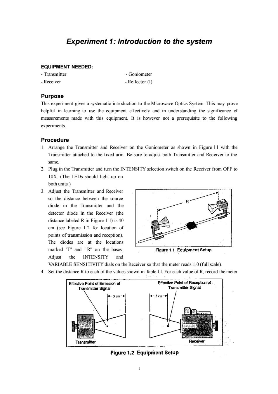
Experiment 1:Introduction to the system EQUIPMENT NEEDED: Transmitter -Goniometer -Receiver Reflector (1) Purpose This experiment gives a systematic introduction to the Microwave Optics System.This may prove helpful in learning to use the equipment effectively and in understanding the significance of measurements made with this equipment.It is however not a prerequisite to the following experiments. Procedure 1.Arrange the Transmitter and Receiver on the Goniometer as shown in Figure 1.I with the Transmitter attached to the fixed arm.Bc sure to adjust both Transmitter and Receiver to the same. 2.Plug in the Transmitter and turn the INTENSITY selection switch on the Receiver from OFF to 10X.(The LEDs should light up on both units. 3.Adjust the Transmitter and Receiver so the distance between the source diode in the Transmitter and the detector diode in the Receiver (the distance labeled R in Figure 1.1)is 40 cm (see Figure 1.2 for location of points of transmission and reception). The diodes are at the locations marked "T"and "R"on the bases. Figure 1.1 Equlpment Setup Adjust the INTENSITY and VARIABLE SENSITIVITY dials on the Receiver so that the meter reads 1.0(full scale). 4.Set the distance R to each of the values shown in Table 1.I.For each value of R,record the meter Effective Point of Emission of Effective Point of Reception of Transmitter Signal Transmitter Signal -5 cm- Transmitter Receiver Figure 1.2 Equipment Setup1 Experiment 1: Introduction to the system EQUIPMENT NEEDED: - Transmitter - Goniometer - Receiver - Reflector (l) Purpose This experiment gives a systematic introduction to the Microwave Optics System. This may prove helpful in learning to use the equipment effectively and in understanding the significance of measurements made with this equipment. It is however not a prerequisite to the following experiments. Procedure 1. Arrange the Transmitter and Receiver on the Goniometer as shown in Figure l.l with the Transmitter attached to the fixed arm. Bc sure to adjust both Transmitter and Receiver to the same. 2. Plug in the Transmitter and turn the INTENSITY selection switch on the Receiver from OFF to 10X. (The LEDs should light up on both units.) 3. Adjust the Transmitter and Receiver so the distance between the source diode in the Transmitter and the detector diode in the Receiver (the distance labeled R in Figure 1.1) is 40 cm (see Figure 1.2 for location of points of transmission and reception). The diodes are at the locations marked ''T'' and '`R'' on the bases. Adjust the INTENSITY and VARIABLE SENSITIVITY dials on the Receiver so that the meter reads 1.0 (full scale). 4. Set the distance R to each of the values shown in Table l.l. For each value of R, record the meter