正在加载图片...
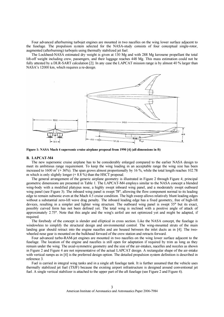
Four advanced afterburning turbojet engines are mounted in two nacelles on the wing lower surface adjacent to the fuselage.The propulsion system selected for the NASA-study consists of four conceptual single-rotor, augmented(afterburning)turbojets using thermally stabilized jet fuel. The Lockheed-NASA estimated dry weight is given at 130 Mg and with 288 Mg kerosene propellant the total lift-off weight including crew,passengers,and their luggage reaches 448 Mg.This mass estimation could not be fully attested by a DLR-SART calculation [2].In any case the LAPCAT mission range is by almost 40%larger than NASA's 12000 km,which requires a re-design. 1530 10.0 32s 12125 Figure 1:NASA Mach 4 supersonic cruise airplane proposal from 1990 [4](all dimensions in ft) B.LAPCAT-M4 The new supersonic cruise airplane has to be considerably enlarged compared to the earlier NASA design to meet its ambitious range requirement.To keep the wing loading in an acceptable range the wing size has been increased to 1600 m2(+36%).The span grows almost proportionally by 16%,while the total length reaches 102.78 m which is only slightly longer(+8.8%)than the HSCT proposal. The general arrangement of the generic airplane geometry is illustrated in Figure 2 through Figure 4;principal geometric dimensions are presented in Table 1.The LAPCAT-M4 employs similar to the NASA concept a blended wing-body with a modified platypus nose,a highly swept inboard wing panel,and a moderately swept outboard wing panel (see Figure 3).The inboard wing panel is swept 78,allowing the flow component normal to its leading edge to remain subsonic even at the Mach 4.5 cruise condition.The high sweep allows relatively blunt leading edges without a substantial zero-lift wave drag penalty.The inboard leading edge has a fixed geometry,free of high-lift devices,resulting in a simpler and lighter wing structure.The outboard wing panel is swept 55 but its exact, possibly curved form has not been defined yet.The total wing is inclined with a positive angle of attack of approximately 2.75.Note that this angle and the wing's airfoil are not optimized yet and might be adapted,if required. The forebody of the concept is slender and elliptical in cross section.Like the NASA concept,the fuselage is windowless to simplify the structural design and environmental control.The wing-mounted struts of the main landing gear should retract into the engine nacelles and are housed between the inlet ducts as in [4].The two- wheeled nose gear is mounted on the bulkhead forward of the crew station and retracts forward. Four advanced turbo-RAM-jet engines are mounted in two nacelles on the wing lower surface adjacent to the fuselage.The location of the engine and nacelles is still open for adaptation if required by trim as long as they remain under the wing.The axial-symmetric geometry and the size of the air-intakes,nacelles and nozzles as shown in Figure 2 and Figure 4 are not representative of the actual LAPCAT design.A rectangular shape of the air-intake with vertical ramps as in [4]is the preferred design option.The detailed propulsion system definition is described in reference 3. Fuel is carried in integral wing tanks and in a single aft fuselage tank.It is further assumed that the vehicle uses thermally stabilized jet fuel (TSJF)because the existing airport infrastructure is designed around conventional jet fuel.A single vertical stabilizer is attached to the upper part of the aft fuselage(see Figure 2 and Figure 4). 3 American Institute of Aeronautics and Astronautics Paper 2006-7984American Institute of Aeronautics and Astronautics Paper 2006-7984 3 Four advanced afterburning turbojet engines are mounted in two nacelles on the wing lower surface adjacent to the fuselage. The propulsion system selected for the NASA-study consists of four conceptual single-rotor, augmented (afterburning) turbojets using thermally stabilized jet fuel. The Lockheed-NASA estimated dry weight is given at 130 Mg and with 288 Mg kerosene propellant the total lift-off weight including crew, passengers, and their luggage reaches 448 Mg. This mass estimation could not be fully attested by a DLR-SART calculation [2]. In any case the LAPCAT mission range is by almost 40 % larger than NASA’s 12000 km, which requires a re-design. Figure 1: NASA Mach 4 supersonic cruise airplane proposal from 1990 [4] (all dimensions in ft) B. LAPCAT-M4 The new supersonic cruise airplane has to be considerably enlarged compared to the earlier NASA design to meet its ambitious range requirement. To keep the wing loading in an acceptable range the wing size has been increased to 1600 m2 (+ 36%). The span grows almost proportionally by 16 %, while the total length reaches 102.78 m which is only slightly longer (+ 8.8 %) than the HSCT proposal. The general arrangement of the generic airplane geometry is illustrated in Figure 2 through Figure 4; principal geometric dimensions are presented in Table 1. The LAPCAT-M4 employs similar to the NASA concept a blended wing-body with a modified platypus nose, a highly swept inboard wing panel, and a moderately swept outboard wing panel (see Figure 3). The inboard wing panel is swept 78°, allowing the flow component normal to its leading edge to remain subsonic even at the Mach 4.5 cruise condition. The high sweep allows relatively blunt leading edges without a substantial zero-lift wave drag penalty. The inboard leading edge has a fixed geometry, free of high-lift devices, resulting in a simpler and lighter wing structure. The outboard wing panel is swept 55° but its exact, possibly curved form has not been defined yet. The total wing is inclined with a positive angle of attack of approximately 2.75°. Note that this angle and the wing's airfoil are not optimized yet and might be adapted, if required. The forebody of the concept is slender and elliptical in cross section. Like the NASA concept, the fuselage is windowless to simplify the structural design and environmental control. The wing-mounted struts of the main landing gear should retract into the engine nacelles and are housed between the inlet ducts as in [4]. The twowheeled nose gear is mounted on the bulkhead forward of the crew station and retracts forward. Four advanced turbo-RAM-jet engines are mounted in two nacelles on the wing lower surface adjacent to the fuselage. The location of the engine and nacelles is still open for adaptation if required by trim as long as they remain under the wing. The axial-symmetric geometry and the size of the air-intakes, nacelles and nozzles as shown in Figure 2 and Figure 4 are not representative of the actual LAPCAT design. A rectangular shape of the air-intake with vertical ramps as in [4] is the preferred design option. The detailed propulsion system definition is described in reference 3. Fuel is carried in integral wing tanks and in a single aft fuselage tank. It is further assumed that the vehicle uses thermally stabilized jet fuel (TSJF) because the existing airport infrastructure is designed around conventional jet fuel. A single vertical stabilizer is attached to the upper part of the aft fuselage (see Figure 2 and Figure 4)