正在加载图片...
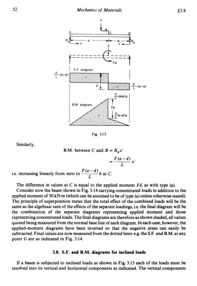
52 Mechanics of Materials $3.8 S.F diagram F (d+b) L E-(a-o) F(d+b)a B.M.diagram Fd F(a-d)b Fig.3.13. Similarly, B.M.between C and B=Rax' -F(a-d)x L i.e.increasing linearly from zero to F(a-d)bat C. L The difference in values at C is equal to the applied moment Fd,as with type(a). Consider now the beam shown in Fig.3.14 carrying concentrated loads in addition to the applied moment of 30 kNm(which can be assumed to be of type(a)unless otherwise stated). The principle of superposition states that the total effect of the combined loads will be the same as the algebraic sum of the effects of the separate loadings,i.e.the final diagram will be the combination of the separate diagrams representing applied moment and those representing concentrated loads.The final diagrams are therefore as shown shaded,all values quoted being measured from the normal base line of each diagram.In each case,however,the applied-moment diagrams have been inverted so that the negative areas can easily be subtracted.Final values are now measured from the dotted lines:e.g.the S.F.and B.M.at any point G are as indicated in Fig.3.14. 3.8.S.F.and B.M.diagrams for inclined loads If a beam is subjected to inclined loads as shown in Fig.3.15 each of the loads must be resolved into its vertical and horizontal components as indicated.The vertical components52 Mechanics of Materials ($3.8 F adb ------- ----- ------- ----- f ‘Fd 7 I S F diagram I Fig. 3.13. Similarly, B.M. between C and B = R,x’ F(a-d) L X’ - -- F(a-d) L i.e. increasing linearly from zero to ____ b at C. The difference in values at C is equal to the applied moment Fd, as with type (a). Consider now the beam shown in Fig. 3.14 carrying concentrated loads in addition to the applied moment of 30 kN m (which can be assumed to be of type (a) unless otherwise stated). The principle of superposition states that the total effect of the combined loads will be the same as the algebraic sum of the effects of the separate loadings, i.e. the final diagram will be the combination of the separate diagrams representing applied moment and those representing concentrated loads. The final diagrams are therefore as shown shaded, all values quoted being measured from the normal base line of each diagram. In each case, however, the applied-moment diagrams have been inverted so that the negative areas can easily be subtracted. Final values are now measured from the dotted lines: e.g. the S.F. and B.M. at any point G are as indicated in Fig. 3.14. 3.8. S.F. and B.M. diagrams for inclined loads If a beam is subjected to inclined loads as shown in Fig. 3.15 each of the loads must be resolved into its vertical and horizontal components as indicated. The vertical components