正在加载图片...
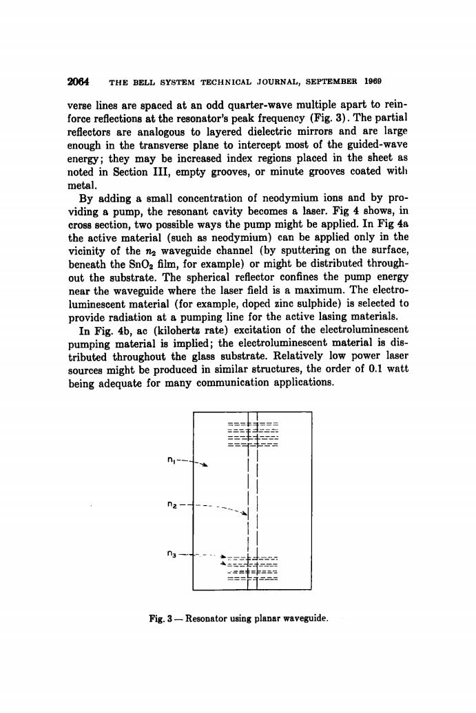
2064 THE BELL SYSTEM TECHNICAL JOURNAL,SEPTEMBER 1969 verse lines are spaced at an odd quarter-wave multiple apart to rein- force reflections at the resonator's peak frequency (Fig.3).The partial reflectors are analogous to layered dielectric mirrors and are large enough in the transverse plane to intercept most of the guided-wave energy;they may be increased index regions placed in the sheet as noted in Section III,empty grooves,or minute grooves coated with metal. By adding a small concentration of neodymium ions and by pro- viding a pump,the resonant cavity becomes a laser.Fig 4 shows,in cross section,two possible ways the pump might be applied.In Fig 4a the active material (such as neodymium)can be applied only in the vicinity of the na waveguide channel (by sputtering on the surface, beneath the SnOz film,for example)or might be distributed through- out the substrate.The spherical reflector confines the pump energy near the waveguide where the laser field is a maximum.The electro- luminescent material (for example,doped zinc sulphide)is selected to provide radiation at a pumping line for the active lasing materials. In Fig.4b,ac (kilohertz rate)excitation of the electroluminescent pumping material is implied;the electroluminescent material is dis- tributed throughout the glass substrate.Relatively low power laser sources might be produced in similar structures,the order of 0.1 watt being adequate for many communication applications. n Fig.3-Resonator using planar waveguide.2064 THE BELL SYSTEM TECHNICAL JOURNAL, SEPTEMBER 1969 Fig. 3 — Resonator using planar waveguide. verse lines are spaced a t an odd quarter-wave multiple apart to reinforce reflections a t the resonator's peak frequency (Fig. 3). The partial reflectors are analogous to layered dielectric mirrors and are large enough in the transverse plane to intercept most of the guided-wave energy; they ma y be increased index regions placed in the sheet as noted in Section III, empty grooves, or minute grooves coated with metal. By adding a small concentration of neodymium ions and by providing a pump, the resonant cavity becomes a laser. Fig 4 shows, in cross section, two possible ways the pump might be applied. In Fig 4a the active material (such as neodymium) can be applied only in the vicinity of the waveguide channel (by sputtering on the surface, beneath the Sn02 fihn, for example) or might be distributed throughout the substrate. The spherical reflector confines the pump energy near the waveguide where the laser field is a maximum. The electroluminescent material (for example, doped zinc sulphide) is selected to provide radiation at a pumping line for the active lasing materials. In Fig. 4b, ac (kilohertz rate) excitation of the electroluminescent pumping material is implied; the electroluminescent material is distributed throughout the glass substrate. Relatively low power laser sources might be produced in similar structures, the order of 0.1 watt being adequate for many communication applications