正在加载图片...
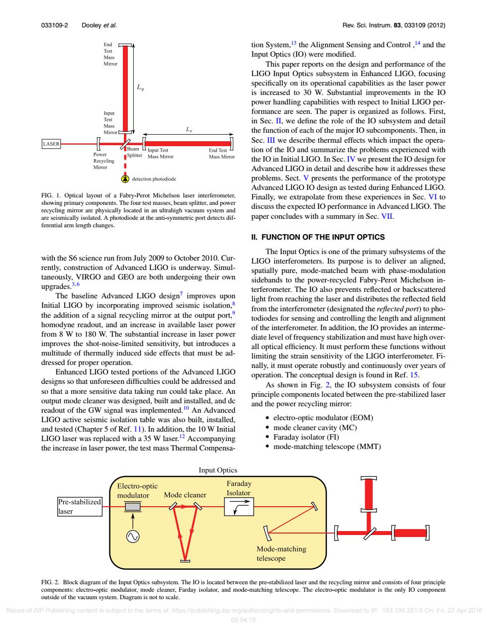
033109-2 Dooley et al Rev.Sci.Instrum.83,033109(2012) End tion System,13 the Alignment Sensing and Control,14 and the Input Optics (IO)were modified. Mirror This paper reports on the design and performance of the LIGO Input Optics subsystem in Enhanced LIGO,focusing specifically on its operational capabilities as the laser power is increased to 30 W.Substantial improvements in the IO power handling capabilities with respect to Initial LIGO per- Input formance are seen.The paper is organized as follows.First, Test in Sec.II.we define the role of the IO subsystem and detail Mass the function of each of the major IO subcomponents.Then,in LASER Sec.III we describe thermal effects which impact the opera- Beam Input Test End Test tion of the IO and summarize the problems experienced with Power Splitter Mass Mirror Mass Mirror Recycling the IO in Initial LIGO.In Sec.IV we present the IO design for Mirror Advanced LIGO in detail and describe how it addresses these ④ detection photodiode problems.Sect.V presents the performance of the prototype Advanced LIGO IO design as tested during Enhanced LIGO. FIG.1.Optical layout of a Fabry-Perot Michelson laser interferometer, Finally,we extrapolate from these experiences in Sec.VI to showing primary components.The four test masses,beam splitter,and power recycling mirror are physically located in an ultrahigh vacuum system and discuss the expected IO performance in Advanced LIGO.The are seismically isolated.A photodiode at the anti-symmetric port detects dif- paper concludes with a summary in Sec.VII. ferential arm length changes. II.FUNCTION OF THE INPUT OPTICS The Input Optics is one of the primary subsystems of the with the S6 science run from July 2009 to October 2010.Cur- LIGO interferometers.Its purpose is to deliver an aligned, rently,construction of Advanced LIGO is underway.Simul- spatially pure,mode-matched beam with phase-modulation taneously,VIRGO and GEO are both undergoing their own upgrades.3.6 sidebands to the power-recycled Fabry-Perot Michelson in- terferometer.The IO also prevents reflected or backscattered The baseline Advanced LIGO design?improves upon light from reaching the laser and distributes the reflected field Initial LIGO by incorporating improved seismic isolation,8 from the interferometer(designated the reflected port)to pho- the addition of a signal recycling mirror at the output port, todiodes for sensing and controlling the length and alignment homodyne readout,and an increase in available laser power of the interferometer.In addition,the IO provides an interme- from 8 W to 180 W.The substantial increase in laser power diate level of frequency stabilization and must have high over- improves the shot-noise-limited sensitivity,but introduces a all optical efficiency.It must perform these functions without multitude of thermally induced side effects that must be ad- limiting the strain sensitivity of the LIGO interferometer.Fi- dressed for proper operation. nally,it must operate robustly and continuously over years of Enhanced LIGO tested portions of the Advanced LIGO operation.The conceptual design is found in Ref.15. designs so that unforeseen difficulties could be addressed and As shown in Fig.2,the IO subsystem consists of four so that a more sensitive data taking run could take place.An principle components located between the pre-stabilized laser output mode cleaner was designed,built and installed,and dc readout of the GW signal was implemented.10 An Advanced and the power recycling mirror: LIGO active seismic isolation table was also built,installed. electro-optic modulator(EOM) and tested(Chapter 5 of Ref.11).In addition,the 10 W Initial mode cleaner cavity (MC) LIGO laser was replaced with a 35 W laser.12 Accompanying 。Faraday isolator(F) the increase in laser power,the test mass Thermal Compensa- mode-matching telescope (MMT) Input Optics Electro-optic Faraday modulator Mode cleaner Isolator Pre-stabilized laser Mode-matching telescope FIG.2.Block diagram of the Input Optics subsystem.The IO is located between the pre-stabilized laser and the recycling mirror and consists of four principle components:electro-optic modulator,mode cleaner,Farday isolator,and mode-matching telescope.The electro-optic modulator is the only IO component outside of the vacuum system.Diagram is not to scale. Reuse of AlP Publishing content is subject to the terms at:https://publishing.aip.org/authors/rights-and-permissions.Download to IP:183.195.251.6 On:Fri.22 Apr 2016 00:54:10033109-2 Dooley et al. Rev. Sci. Instrum. 83, 033109 (2012) FIG. 1. Optical layout of a Fabry-Perot Michelson laser interferometer, showing primary components. The four test masses, beam splitter, and power recycling mirror are physically located in an ultrahigh vacuum system and are seismically isolated. A photodiode at the anti-symmetric port detects differential arm length changes. with the S6 science run from July 2009 to October 2010. Currently, construction of Advanced LIGO is underway. Simultaneously, VIRGO and GEO are both undergoing their own upgrades.3, 6 The baseline Advanced LIGO design7 improves upon Initial LIGO by incorporating improved seismic isolation,8 the addition of a signal recycling mirror at the output port,9 homodyne readout, and an increase in available laser power from 8 W to 180 W. The substantial increase in laser power improves the shot-noise-limited sensitivity, but introduces a multitude of thermally induced side effects that must be addressed for proper operation. Enhanced LIGO tested portions of the Advanced LIGO designs so that unforeseen difficulties could be addressed and so that a more sensitive data taking run could take place. An output mode cleaner was designed, built and installed, and dc readout of the GW signal was implemented.10 An Advanced LIGO active seismic isolation table was also built, installed, and tested (Chapter 5 of Ref. 11). In addition, the 10 W Initial LIGO laser was replaced with a 35 W laser.12 Accompanying the increase in laser power, the test mass Thermal Compensation System,13 the Alignment Sensing and Control ,14 and the Input Optics (IO) were modified. This paper reports on the design and performance of the LIGO Input Optics subsystem in Enhanced LIGO, focusing specifically on its operational capabilities as the laser power is increased to 30 W. Substantial improvements in the IO power handling capabilities with respect to Initial LIGO performance are seen. The paper is organized as follows. First, in Sec. II, we define the role of the IO subsystem and detail the function of each of the major IO subcomponents. Then, in Sec. III we describe thermal effects which impact the operation of the IO and summarize the problems experienced with the IO in Initial LIGO. In Sec. IV we present the IO design for Advanced LIGO in detail and describe how it addresses these problems. Sect. V presents the performance of the prototype Advanced LIGO IO design as tested during Enhanced LIGO. Finally, we extrapolate from these experiences in Sec. VI to discuss the expected IO performance in Advanced LIGO. The paper concludes with a summary in Sec. VII. II. FUNCTION OF THE INPUT OPTICS The Input Optics is one of the primary subsystems of the LIGO interferometers. Its purpose is to deliver an aligned, spatially pure, mode-matched beam with phase-modulation sidebands to the power-recycled Fabry-Perot Michelson interferometer. The IO also prevents reflected or backscattered light from reaching the laser and distributes the reflected field from the interferometer (designated the reflected port) to photodiodes for sensing and controlling the length and alignment of the interferometer. In addition, the IO provides an intermediate level of frequency stabilization and must have high overall optical efficiency. It must perform these functions without limiting the strain sensitivity of the LIGO interferometer. Finally, it must operate robustly and continuously over years of operation. The conceptual design is found in Ref. 15. As shown in Fig. 2, the IO subsystem consists of four principle components located between the pre-stabilized laser and the power recycling mirror: electro-optic modulator (EOM) mode cleaner cavity (MC) Faraday isolator (FI) mode-matching telescope (MMT) FIG. 2. Block diagram of the Input Optics subsystem. The IO is located between the pre-stabilized laser and the recycling mirror and consists of four principle components: electro-optic modulator, mode cleaner, Farday isolator, and mode-matching telescope. The electro-optic modulator is the only IO component outside of the vacuum system. Diagram is not to scale. Reuse of AIP Publishing content is subject to the terms at: https://publishing.aip.org/authors/rights-and-permissions. Download to IP: 183.195.251.6 On: Fri, 22 Apr 2016 00:54:10����