正在加载图片...
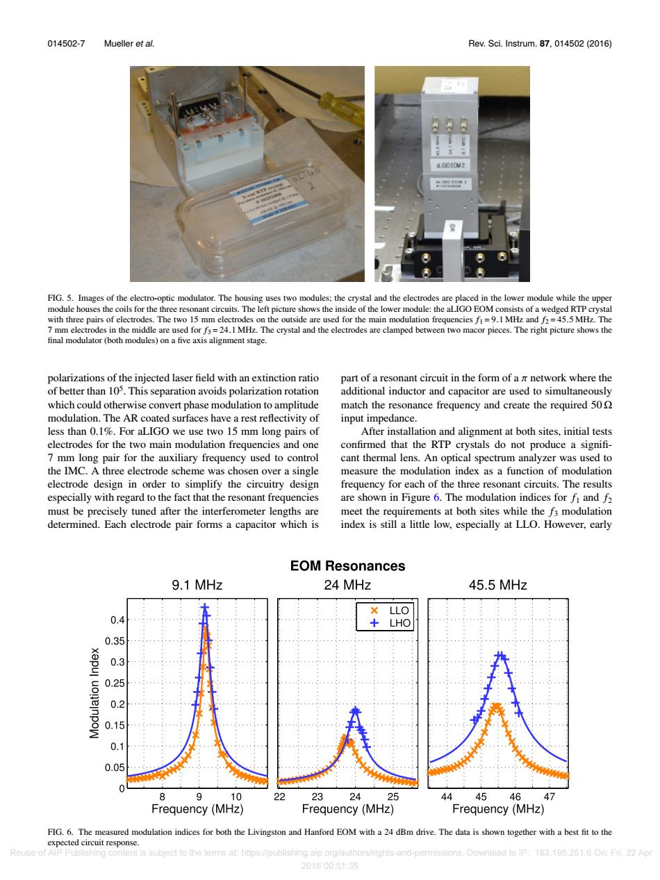
014502-7 Mueller et al. Rev.Sci.Instrum.87,014502(2016) 898 LGO EOM2 FIG.5.Images of the electro-optic modulator.The housing uses two modules:the crystal and the electrodes are placed in the lower module while the upper module houses the coils for the three resonant circuits.The left picture shows the inside of the lower module:the aLIGO EOM consists of a wedged RTP crystal with three pairs of electrodes.The two 15 mm electrodes on the outside are used for the main modulation frequencies f=9.1 MHz and f2=45.5 MHz.The 7 mm electrodes in the middle are used for f3=24.1 MHz.The crystal and the electrodes are clamped between two macor pieces.The right picture shows the final modulator (both modules)on a five axis alignment stage. polarizations of the injected laser field with an extinction ratio part of a resonant circuit in the form of a m network where the of better than 105.This separation avoids polarization rotation additional inductor and capacitor are used to simultaneously which could otherwise convert phase modulation to amplitude match the resonance frequency and create the required 50 modulation.The AR coated surfaces have a rest reflectivity of input impedance. less than 0.1%.For aLIGO we use two 15 mm long pairs of After installation and alignment at both sites,initial tests electrodes for the two main modulation frequencies and one confirmed that the RTP crystals do not produce a signifi- 7 mm long pair for the auxiliary frequency used to control cant thermal lens.An optical spectrum analyzer was used to the IMC.A three electrode scheme was chosen over a single measure the modulation index as a function of modulation electrode design in order to simplify the circuitry design frequency for each of the three resonant circuits.The results especially with regard to the fact that the resonant frequencies are shown in Figure 6.The modulation indices for fi and f2 must be precisely tuned after the interferometer lengths are meet the requirements at both sites while the f3 modulation determined.Each electrode pair forms a capacitor which is index is still a little low,especially at LLO.However,early EOM Resonances 9.1 MHz 24 MHz 45.5 MHz LLO 0.4 +LHO 0.35 0.3 0.25 0.2 0.15 0.1 0.05 9 10 22 23 24 25 44 454647 Frequency(MHz) Frequency(MHz) Frequency(MHz) FIG.6.The measured modulation indices for both the Livingston and Hanford EOM with a 24 dBm drive.The data is shown together with a best fit to the expected circuit response. Reuse of AlP Publishing content is subject to the terms at:https://publishing.aip.org/authors/rights-and-permissions.Download to IP:183.195.251.6 On:Fri.22 Apr 2016005135014502-7 Mueller et al. Rev. Sci. Instrum. 87, 014502 (2016) FIG. 5. Images of the electro-optic modulator. The housing uses two modules; the crystal and the electrodes are placed in the lower module while the upper module houses the coils for the three resonant circuits. The left picture shows the inside of the lower module: the aLIGO EOM consists of a wedged RTP crystal with three pairs of electrodes. The two 15 mm electrodes on the outside are used for the main modulation frequencies f1 = 9.1 MHz and f2 = 45.5 MHz. The 7 mm electrodes in the middle are used for f3 = 24.1 MHz. The crystal and the electrodes are clamped between two macor pieces. The right picture shows the final modulator (both modules) on a five axis alignment stage. polarizations of the injected laser field with an extinction ratio of better than 105 . This separation avoids polarization rotation which could otherwise convert phase modulation to amplitude modulation. The AR coated surfaces have a rest reflectivity of less than 0.1%. For aLIGO we use two 15 mm long pairs of electrodes for the two main modulation frequencies and one 7 mm long pair for the auxiliary frequency used to control the IMC. A three electrode scheme was chosen over a single electrode design in order to simplify the circuitry design especially with regard to the fact that the resonant frequencies must be precisely tuned after the interferometer lengths are determined. Each electrode pair forms a capacitor which is part of a resonant circuit in the form of a π network where the additional inductor and capacitor are used to simultaneously match the resonance frequency and create the required 50 Ω input impedance. After installation and alignment at both sites, initial tests confirmed that the RTP crystals do not produce a significant thermal lens. An optical spectrum analyzer was used to measure the modulation index as a function of modulation frequency for each of the three resonant circuits. The results are shown in Figure 6. The modulation indices for f1 and f2 meet the requirements at both sites while the f3 modulation index is still a little low, especially at LLO. However, early FIG. 6. The measured modulation indices for both the Livingston and Hanford EOM with a 24 dBm drive. The data is shown together with a best fit to the expected circuit response. Reuse of AIP Publishing content is subject to the terms at: https://publishing.aip.org/authors/rights-and-permissions. Download to IP: 183.195.251.6 On: Fri, 22 Apr 2016 00:51:35