正在加载图片...
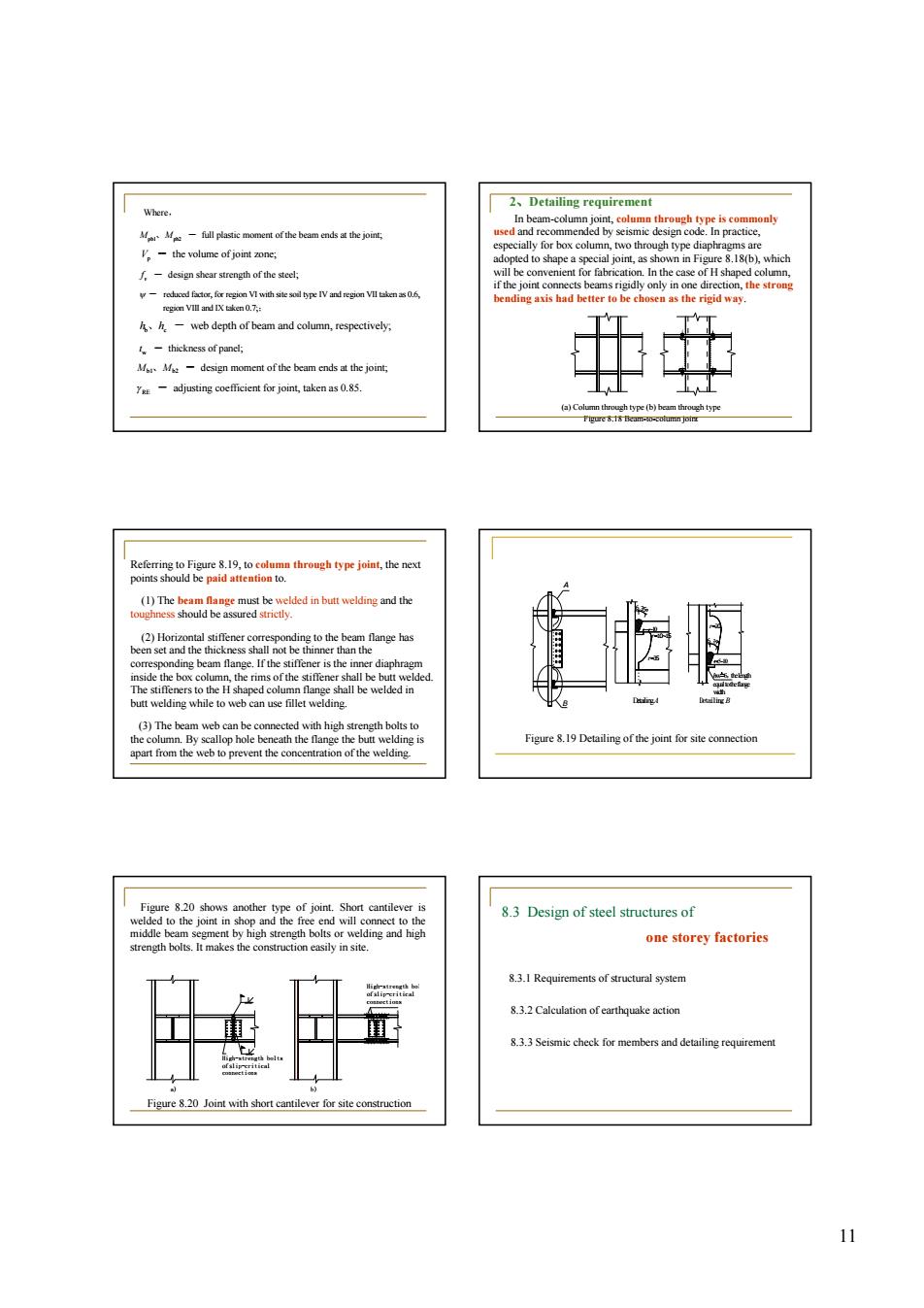
2.Detailing requirement f the beam endshee for bo h of the stecl design m nem of the beam ends the joiet justing ooefcen for joint,taken as0.. 中 the i 到 re 8.20 shows and 83 Design of steel structures of one storey factories 3.I Requirements of yem 8.3.2 Calculstion of earthouake action Seismic chec for members and detaling 1111 reduced factor, for region VI with site soil type IV and region VII taken as 0.6, region VIII and IX taken 0.7; y - ; h h b c 、 - web depth of beam and column, respectively; w t - thickness of panel; b1 b2 M M 、 - design moment of the beam ends at the joint; RE g - adjusting coefficient for joint, taken as 0.85. design shear strength of the steel; v f - pb1 pb2 M M 、 - full plastic moment of the beam ends at the joint; p V - the volume of joint zone; Where, 2、Detailing requirement In beam-column joint, column through type is commonly used and recommended by seismic design code. In practice, especially for box column, two through type diaphragms are adopted to shape a special joint, as shown in Figure 8.18(b), which will be convenient for fabrication. In the case of H shaped column, if the joint connects beams rigidly only in one direction, the strong bending axis had better to be chosen as the rigid way. (a) Column through type (b) beam through type Figure 8.18 Beam-to-column joint Referring to Figure 8.19, to column through type joint, the next points should be paid attention to. (1) The beam flange must be welded in butt welding and the toughness should be assured strictly. (2) Horizontal stiffener corresponding to the beam flange has been set and the thickness shall not be thinner than the corresponding beam flange. If the stiffener is the inner diaphragm inside the box column, the rims of the stiffener shall be butt welded. The stiffeners to the H shaped column flange shall be welded in butt welding while to web can use fillet welding. (3) The beam web can be connected with high strength bolts to the column. By scallop hole beneath the flange the butt welding is apart from the web to prevent the concentration of the welding. 5~10 35° 6 r=20 Detailing A 35° r=35 r=10~15 ~10 6 A B hw=6,the length equaltotheflange width Detailing B Figure 8.19 Detailing of the joint for site connection Figure 8.20 shows another type of joint. Short cantilever is welded to the joint in shop and the free end will connect to the middle beam segment by high strength bolts or welding and high strength bolts. It makes the construction easily in site. Figure 8.20 Joint with short cantilever for site construction High-strength bolts of slip-critical connections a) b) High-strength bolts of slip-critical connections 8.3 Design of steel structures of one storey factories 8.3.1 Requirements of structural system 8.3.2 Calculation of earthquake action 8.3.3 Seismic check for members and detailing requirement