正在加载图片...

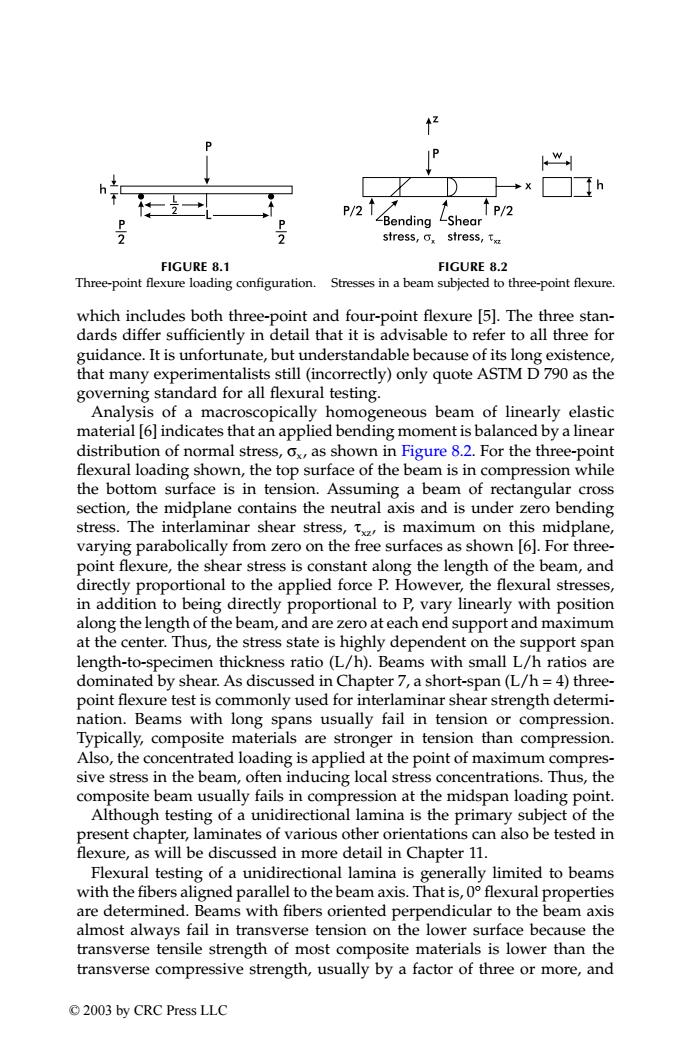
/ w P/2 P/2 0 -Bending -Shear 2 stress,o,stress,t FIGURE 8.1 FIGURE 8.2 Three-point flexure loading configuration. Stresses in a beam subjected to three-point flexure. which includes both three-point and four-point flexure [5].The three stan- dards differ sufficiently in detail that it is advisable to refer to all three for guidance.It is unfortunate,but understandable because of its long existence, that many experimentalists still (incorrectly)only quote ASTM D790 as the governing standard for all flexural testing. Analysis of a macroscopically homogeneous beam of linearly elastic material [6]indicates that an applied bending moment is balanced by a linear distribution of normal stress,ox,as shown in Figure 8.2.For the three-point flexural loading shown,the top surface of the beam is in compression while the bottom surface is in tension.Assuming a beam of rectangular cross section,the midplane contains the neutral axis and is under zero bending stress.The interlaminar shear stress,t,is maximum on this midplane, varying parabolically from zero on the free surfaces as shown [6].For three- point flexure,the shear stress is constant along the length of the beam,and directly proportional to the applied force P.However,the flexural stresses, in addition to being directly proportional to P,vary linearly with position along the length of the beam,and are zero at each end support and maximum at the center.Thus,the stress state is highly dependent on the support span length-to-specimen thickness ratio (L/h).Beams with small L/h ratios are dominated by shear.As discussed in Chapter 7,a short-span(L/h=4)three- point flexure test is commonly used for interlaminar shear strength determi- nation.Beams with long spans usually fail in tension or compression. Typically,composite materials are stronger in tension than compression. Also,the concentrated loading is applied at the point of maximum compres- sive stress in the beam,often inducing local stress concentrations.Thus,the composite beam usually fails in compression at the midspan loading point. Although testing of a unidirectional lamina is the primary subject of the present chapter,laminates of various other orientations can also be tested in flexure,as will be discussed in more detail in Chapter 11. Flexural testing of a unidirectional lamina is generally limited to beams with the fibers aligned parallel to the beam axis.That is,0 flexural properties are determined.Beams with fibers oriented perpendicular to the beam axis almost always fail in transverse tension on the lower surface because the transverse tensile strength of most composite materials is lower than the transverse compressive strength,usually by a factor of three or more,and 2003 by CRC Press LLCwhich includes both three-point and four-point flexure [5]. The three standards differ sufficiently in detail that it is advisable to refer to all three for guidance. It is unfortunate, but understandable because of its long existence, that many experimentalists still (incorrectly) only quote ASTM D 790 as the governing standard for all flexural testing. Analysis of a macroscopically homogeneous beam of linearly elastic material [6] indicates that an applied bending moment is balanced by a linear distribution of normal stress, σx, as shown in Figure 8.2. For the three-point flexural loading shown, the top surface of the beam is in compression while the bottom surface is in tension. Assuming a beam of rectangular cross section, the midplane contains the neutral axis and is under zero bending stress. The interlaminar shear stress, τxz, is maximum on this midplane, varying parabolically from zero on the free surfaces as shown [6]. For threepoint flexure, the shear stress is constant along the length of the beam, and directly proportional to the applied force P. However, the flexural stresses, in addition to being directly proportional to P, vary linearly with position along the length of the beam, and are zero at each end support and maximum at the center. Thus, the stress state is highly dependent on the support span length-to-specimen thickness ratio (L/h). Beams with small L/h ratios are dominated by shear. As discussed in Chapter 7, a short-span (L/h = 4) threepoint flexure test is commonly used for interlaminar shear strength determination. Beams with long spans usually fail in tension or compression. Typically, composite materials are stronger in tension than compression. Also, the concentrated loading is applied at the point of maximum compressive stress in the beam, often inducing local stress concentrations. Thus, the composite beam usually fails in compression at the midspan loading point. Although testing of a unidirectional lamina is the primary subject of the present chapter, laminates of various other orientations can also be tested in flexure, as will be discussed in more detail in Chapter 11. Flexural testing of a unidirectional lamina is generally limited to beams with the fibers aligned parallel to the beam axis. That is, 0° flexural properties are determined. Beams with fibers oriented perpendicular to the beam axis almost always fail in transverse tension on the lower surface because the transverse tensile strength of most composite materials is lower than the transverse compressive strength, usually by a factor of three or more, and FIGURE 8.1 Three-point flexure loading configuration. FIGURE 8.2 Stresses in a beam subjected to three-point flexure. TX001_ch08_Frame Page 122 Saturday, September 21, 2002 4:59 AM © 2003 by CRC Press LLC