正在加载图片...

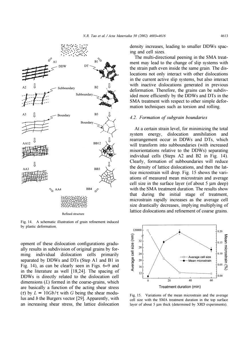
N.R.Tao et al.Acta Materialia 50 (2002)4603-4616 4613 density increases,leading to smaller DDWs spac- ing and cell sizes. The multi-directional peening in the SMA treat- A B ment may lead to the change of slip systems with DDW DT the strain path even inside the same grain.The dis- locations not only interact with other dislocations in the current active slip systems,but also interact B2 with inactive dislocations generated in previous Subboundary deformation.Therefore,the grains can be subdiv- Subboundary ided more efficiently by the DDWs and DTs in the SMA treatment with respect to other simple defor- mation techniques such as torsion and rolling. -Boundary B3 4.2.Formation of subgrain boundaries Boundary At a certain strain level,for minimizing the total system energy,dislocation annihilation and rearrangement occur in DDWs and DTs,which BB12 will transform into subboundaries (with increased misorientations relative to the DDWs)separating individual cells (Steps A2 and B2 in Fig.14). Clearly,formation of subboundaries will reduce AA3 the density of lattice dislocations,and then the lat- tice microstrain will drop.Fig.15 shows the vari- ations of measured mean microstrain and average cell size in the surface layer(of about 5 um deep) AA4 BB4 with the SMA treatment duration.The results show that during the initial stage of treatment, microstrain rapidly increases as the average cell size drastically decreases,implying multiplying of lattice dislocations and refinement of coarse grains. Refined structure Fig.14.A schematic illustration of grain refinement induced by plastic deformation. 120000 0.20 32 0.15 Mean opment of these dislocation configurations gradu- ally results in subdivision of original grains by for- 28 ming individual dislocation cells primarily 云 24 0.10 --Average cell size separated by DDWs and DTs(Step Al and BI in 20 microstrain ◆-Mean microstrain Fig.14),as can be clearly seen in Figs.6-9 and 0.05 8 in the literature as well [18,24].The spacing of 12 -口 DDWs is directly related to the dislocation cell 0.00 dimensions (L)formed in the coarse-grains,which 20 40 60 are basically a function of the acting shear stress Treatment duration(min) (t)by L 10Gb/t with G being the shear modu- Fig.15.Variations of the mean microstrain and the average lus and b the Burgers vector [29].Apparently,with cell size with the SMA treatment duration in the top surface an increasing shear stress,the lattice dislocation layer of about 5 um thick(determined by XRD experiments).N.R. Tao et al. / Acta Materialia 50 (2002) 4603–4616 4613 Fig. 14. A schematic illustration of grain refinement induced by plastic deformation. opment of these dislocation configurations gradually results in subdivision of original grains by forming individual dislocation cells primarily separated by DDWs and DTs (Step A1 and B1 in Fig. 14), as can be clearly seen in Figs. 6–9 and in the literature as well [18,24]. The spacing of DDWs is directly related to the dislocation cell dimensions (L) formed in the coarse-grains, which are basically a function of the acting shear stress (t) by L 10Gb/ τ with G being the shear modulus and b the Burgers vector [29]. Apparently, with an increasing shear stress, the lattice dislocation density increases, leading to smaller DDWs spacing and cell sizes. The multi-directional peening in the SMA treatment may lead to the change of slip systems with the strain path even inside the same grain. The dislocations not only interact with other dislocations in the current active slip systems, but also interact with inactive dislocations generated in previous deformation. Therefore, the grains can be subdivided more efficiently by the DDWs and DTs in the SMA treatment with respect to other simple deformation techniques such as torsion and rolling. 4.2. Formation of subgrain boundaries At a certain strain level, for minimizing the total system energy, dislocation annihilation and rearrangement occur in DDWs and DTs, which will transform into subboundaries (with increased misorientations relative to the DDWs) separating individual cells (Steps A2 and B2 in Fig. 14). Clearly, formation of subboundaries will reduce the density of lattice dislocations, and then the lattice microstrain will drop. Fig. 15 shows the variations of measured mean microstrain and average cell size in the surface layer (of about 5 µm deep) with the SMA treatment duration. The results show that during the initial stage of treatment, microstrain rapidly increases as the average cell size drastically decreases, implying multiplying of lattice dislocations and refinement of coarse grains. Fig. 15. Variations of the mean microstrain and the average cell size with the SMA treatment duration in the top surface layer of about 5 µm thick (determined by XRD experiments)