正在加载图片...
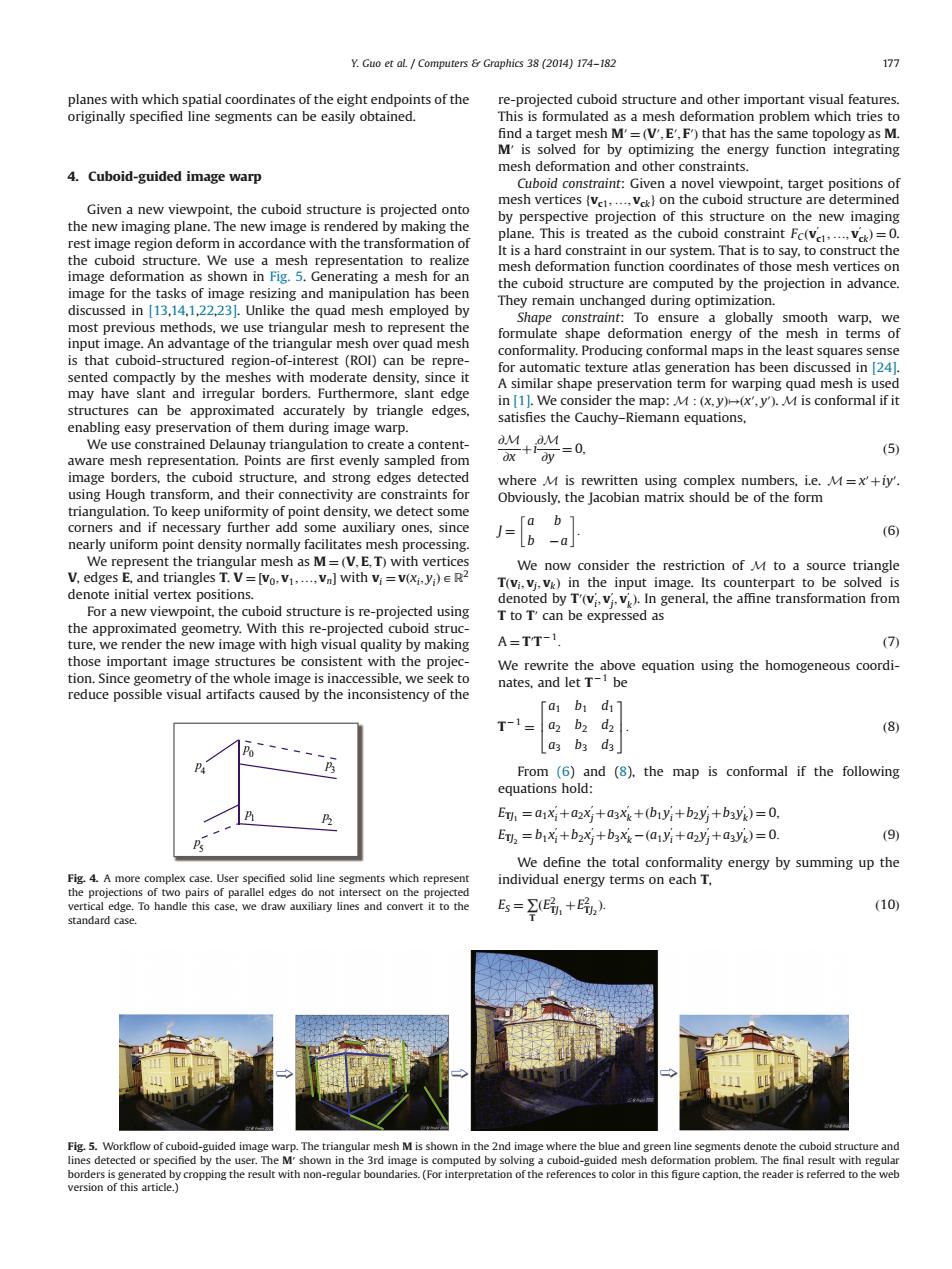
Y.Guo et aL.Computers Graphics 38(2014)174-182 177 planes with which spatial coordinates of the eight endpoints of the re-projected cuboid structure and other important visual features. originally specified line segments can be easily obtained. This is formulated as a mesh deformation problem which tries to find a target mesh M'=(V',E',F')that has the same topology as M. M'is solved for by optimizing the energy function integrating 4.Cuboid-guided image warp mesh deformation and other constraints Cuboid constraint:Given a novel viewpoint,target positions of Given a new viewpoint,the cuboid structure is projected onto mesh vertices (ve.....vk)on the cuboid structure are determined by perspective projection of this structure on the new imaging the new imaging plane.The new image is rendered by making the rest image region deform in accordance with the transformation of plane.This is treated as the cuboid constraint Fc(va.....vk)=0. It is a hard constraint in our system.That is to say,to construct the the cuboid structure.We use a mesh representation to realize mesh deformation function coordinates of those mesh vertices on image deformation as shown in Fig.5.Generating a mesh for an the cuboid structure are computed by the projection in advance. image for the tasks of image resizing and manipulation has been discussed in [13,14,1,22,231.Unlike the quad mesh employed by They remain unchanged during optimization. Shape constraint:To ensure a globally smooth warp,we most previous methods,we use triangular mesh to represent the input image.An advantage of the triangular mesh over quad mesh formulate shape deformation energy of the mesh in terms of conformality.Producing conformal maps in the least squares sense is that cuboid-structured region-of-interest (ROl)can be repre- sented compactly by the meshes with moderate density.since it for automatic texture atlas generation has been discussed in [24] A similar shape preservation term for warping quad mesh is used may have slant and irregular borders.Furthermore,slant edge in [1].We consider the map:M (x,y)(x',y').M is conformal if it structures can be approximated accurately by triangle edges. satisfies the Cauchy-Riemann equations, enabling easy preservation of them during image warp. We use constrained Delaunay triangulation to create a content- +4 ax =0 (5) aware mesh representation.Points are first evenly sampled from image borders,the cuboid structure,and strong edges detected where M is rewritten using complex numbers,i.e.M=x'+iy'. using Hough transform,and their connectivity are constraints for Obviously,the Jacobian matrix should be of the form triangulation.To keep uniformity of point density,we detect some corners and if necessary further add some auxiliary ones,since 「ab1 nearly uniform point density normally facilitates mesh processing. J=(b -a (6) We represent the triangular mesh as M=(V.E.T)with vertices We now consider the restriction of M to a source triangle V,edges E,and triangles T.V=[vo.v1.....Vn]with vi=v(Xi.y)ER2 T(vi.vj.vk)in the input image.Its counterpart to be solved is denote initial vertex positions. denoted by T'(v;,vi,v).In general,the affine transformation from For a new viewpoint,the cuboid structure is re-projected using T to T'can be expressed as the approximated geometry.With this re-projected cuboid struc- ture,we render the new image with high visual quality by making A=TT-1. (7) those important image structures be consistent with the projec- We rewrite the above equation using the homogeneous coordi- tion.Since geometry of the whole image is inaccessible,we seek to nates,and let T-be reduce possible visual artifacts caused by the inconsistency of the Ta bi di T-1 a2 b2 d2 (8) a3 b3 d3 From (6)and (8).the map is conformal if the following equations hold: ET=a1Xi+a2xj+a3Xk+(b1y;+b2yj+b3Vg)=0. ET=b1Xj+b2xj+b3xx-(a1Yi+a2yj+a3Vk)=0. (9) We define the total conformality energy by summing up the Fig.4.A more complex case.User specified solid line segments which represent individual energy terms on each T. the projections of two pairs of parallel edges do not intersect on the projected vertical edge.To handle this case,we draw auxiliary lines and convert it to the Es=+民) (10) standard case. Fig.5.Workflow of cuboid-guided image warp.The triangular mesh M is shown in the 2nd image where the blue and green line segments denote the cuboid structure and lines detected or specified by the user.The M'shown in the 3rd image is computed by solving a cuboid-guided mesh deformation problem.The final result with regular borders is generated by cropping the result with non-regular boundaries.(For interpretation of the references to color in this figure caption,the reader is referred to the web version of this article.)planes with which spatial coordinates of the eight endpoints of the originally specified line segments can be easily obtained. 4. Cuboid-guided image warp Given a new viewpoint, the cuboid structure is projected onto the new imaging plane. The new image is rendered by making the rest image region deform in accordance with the transformation of the cuboid structure. We use a mesh representation to realize image deformation as shown in Fig. 5. Generating a mesh for an image for the tasks of image resizing and manipulation has been discussed in [13,14,1,22,23]. Unlike the quad mesh employed by most previous methods, we use triangular mesh to represent the input image. An advantage of the triangular mesh over quad mesh is that cuboid-structured region-of-interest (ROI) can be represented compactly by the meshes with moderate density, since it may have slant and irregular borders. Furthermore, slant edge structures can be approximated accurately by triangle edges, enabling easy preservation of them during image warp. We use constrained Delaunay triangulation to create a contentaware mesh representation. Points are first evenly sampled from image borders, the cuboid structure, and strong edges detected using Hough transform, and their connectivity are constraints for triangulation. To keep uniformity of point density, we detect some corners and if necessary further add some auxiliary ones, since nearly uniform point density normally facilitates mesh processing. We represent the triangular mesh as M ¼ ðV; E; TÞ with vertices V, edges E, and triangles T. V ¼ ½v0; v1; …; vn with vi ¼ vðxi; yiÞAR2 denote initial vertex positions. For a new viewpoint, the cuboid structure is re-projected using the approximated geometry. With this re-projected cuboid structure, we render the new image with high visual quality by making those important image structures be consistent with the projection. Since geometry of the whole image is inaccessible, we seek to reduce possible visual artifacts caused by the inconsistency of the re-projected cuboid structure and other important visual features. This is formulated as a mesh deformation problem which tries to find a target mesh M′ ¼ ðV′; E′; F′Þ that has the same topology as M. M′ is solved for by optimizing the energy function integrating mesh deformation and other constraints. Cuboid constraint: Given a novel viewpoint, target positions of mesh vertices fvc1; …; vckg on the cuboid structure are determined by perspective projection of this structure on the new imaging plane. This is treated as the cuboid constraint FCðv′ c1; …; v′ ckÞ ¼ 0. It is a hard constraint in our system. That is to say, to construct the mesh deformation function coordinates of those mesh vertices on the cuboid structure are computed by the projection in advance. They remain unchanged during optimization. Shape constraint: To ensure a globally smooth warp, we formulate shape deformation energy of the mesh in terms of conformality. Producing conformal maps in the least squares sense for automatic texture atlas generation has been discussed in [24]. A similar shape preservation term for warping quad mesh is used in [1]. We consider the map: M : ðx; yÞ↦ðx′; y′Þ. M is conformal if it satisfies the Cauchy–Riemann equations, ∂M ∂x þi ∂M ∂y ¼ 0; ð5Þ where M is rewritten using complex numbers, i.e. M ¼ x′þiy′. Obviously, the Jacobian matrix should be of the form J ¼ a b b a : ð6Þ We now consider the restriction of M to a source triangle Tðvi; vj; vkÞ in the input image. Its counterpart to be solved is denoted by T′ðv′ i ; v′ j ; v′ kÞ. In general, the affine transformation from T to T′ can be expressed as A ¼ T′T 1: ð7Þ We rewrite the above equation using the homogeneous coordinates, and let T 1 be T 1 ¼ a1 b1 d1 a2 b2 d2 a3 b3 d3 2 6 4 3 7 5: ð8Þ From (6) and (8), the map is conformal if the following equations hold: ETJ1 ¼ a1x′ i þa2x′ j þa3x′ kþ ðb1y′ i þb2y′ j þb3y′ kÞ ¼ 0; ETJ2 ¼ b1x′ i þb2x′ j þb3x′ k ða1y′ i þa2y′ j þa3y′ kÞ ¼ 0: ð9Þ We define the total conformality energy by summing up the individual energy terms on each T, ES ¼ ∑ T ðE2 TJ1 þE2 TJ2 Þ: ð10Þ p0 1p 2p 3 p 4p 5 p Fig. 4. A more complex case. User specified solid line segments which represent the projections of two pairs of parallel edges do not intersect on the projected vertical edge. To handle this case, we draw auxiliary lines and convert it to the standard case. Fig. 5. Workflow of cuboid-guided image warp. The triangular mesh M is shown in the 2nd image where the blue and green line segments denote the cuboid structure and lines detected or specified by the user. The M′ shown in the 3rd image is computed by solving a cuboid-guided mesh deformation problem. The final result with regular borders is generated by cropping the result with non-regular boundaries. (For interpretation of the references to color in this figure caption, the reader is referred to the web version of this article.) Y. Guo et al. / Computers & Graphics 38 (2014) 174–182 177��