正在加载图片...
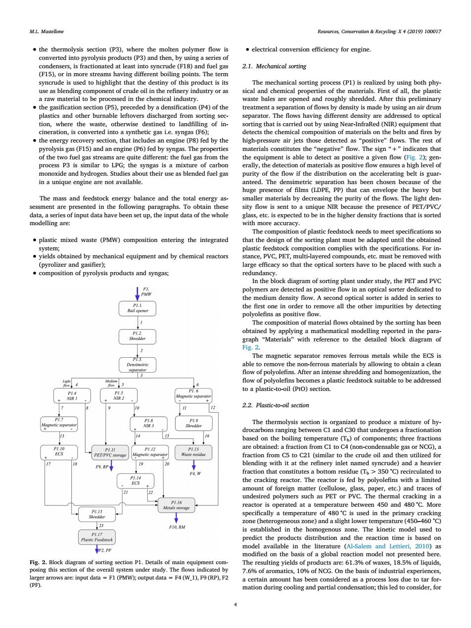
M.L.Mastellone Resources,Conservation Recycling:X 4(2019)100017 the thermolysis section (P3),where the molten polymer flow is electrical conversion efficiency for engine. converted into pyrolysis products(P3)and then,by using a series of condensers,is fractionated at least into syncrude (F18)and fuel gas 2.1.Mechanical sorting (F15),or in more streams having different boiling points.The term syncrude is used to highlight that the destiny of this product is its The mechanical sorting process (P1)is realized by using both phy- use as blending component of crude oil in the refinery industry or as sical and chemical properties of the materials.First of all,the plastic a raw material to be processed in the chemical industry. waste bales are opened and roughly shredded.After this preliminary the gasification section(P5),preceded by a densification(P4)of the treatment a separation of flows by density is made by using an air drum plastics and other burnable leftovers discharged from sorting sec- separator.The flows having different density are addressed to optical tion,where the waste,otherwise destined to landfilling of in- sorting that is carried out by using Near-InfraRed(NIR)equipment that cineration,is converted into a synthetic gas i.e.syngas (F6); detects the chemical composition of materials on the belts and fires by the energy recovery section,that includes an engine (P8)fed by the high-pressure air jets those detected as "positive"flows.The rest of pyrolysis gas(F15)and an engine (P6)fed by syngas.The properties materials constitutes the“negative'”flow.The sign“+”indicates that of the two fuel gas streams are quite different:the fuel gas from the the equipment is able to detect as positive a given flow (Fig.2);gen. process P3 is similar to LPG;the syngas is a mixture of carbon erally,the detection of materials as positive flow ensures a high level of monoxide and hydrogen.Studies about their use as blended fuel gas purity of the flow if the distribution on the accelerating belt is guar- in a unique engine are not available. anteed.The densimetric separation has been chosen because of the huge presence of films(LDPE,PP)that can envelope the heavy but The mass and feedstock energy balance and the total energy as- smaller materials by decreasing the purity of the flows.The light den- sessment are presented in the following paragraphs.To obtain these sity flow is sent to a unique NIR because the presence of PET/PVC/ data,a series of input data have been set up,the input data of the whole glass,etc.is expected to be in the higher density fractions that is sorted modelling are: with more accuracy. The composition of plastic feedstock needs to meet specifications so plastic mixed waste (PMW)composition entering the integrated that the design of the sorting plant must be adapted until the obtained system; plastic feedstock composition complies with the specifications.For in- yields obtained by mechanical equipment and by chemical reactors stance,PVC,PET,multi-layered compounds,etc.must be removed with (pyrolizer and gasifier); large efficacy so that the optical sorters have to be placed with such a composition of pyrolysis products and syngas; redundancy. In the block diagram of sorting plant under study,the PET and PVC polymers are detected as positive flow in an optical sorter dedicated to the medium density flow.A second optical sorter is added in series to the first one in order to remove all the other impurities by detecting polyolefins as positive flow. The composition of material flows obtained by the sorting has been obtained by applying a mathematical modelling reported in the para- hredder graph "Materials"with reference to the detailed block diagram of Fig.2. The magnetic separator removes ferrous metals while the ECS is able to remove the non-ferrous materials by allowing to obtain a clean flow of polyolefins.After an intense shredding and homogenization,the flow of polyolefins becomes a plastic feedstock suitable to be addressed to a plastic-to-oil (Pto)section. PL4 P1.5 NIR 2 + 9 2.2.Plastic-to-oil section P7 The thermolysis section is organized to produce a mixture of hy- drocarbons ranging between Cl and C30 that undergoes a fractionation based on the boiling temperature (Tp)of components;three fractions PII P1.12 P13 are obtained:a fraction from C1 to C4 (non-condensable gas or NCG),a PETPVC storage fraction from C5 to C21(similar to the crude oil and then utilized for F段RP 2 blending with it at the refinery inlet named syncrude)and a heavier 下4, fraction that constitutes a bottom residue (T>350C)recirculated to ECS the cracking reactor.The reactor is fed by polyolefins with a limited amount of foreign matter (cellulose,glass,paper,etc.)and traces of undesired polymers such as PET or PVC.The thermal cracking in a P1.16 Metals storage reactor is operated at a temperature between 450 and 480'C.More specifically a temperature of 480'C is used in the primary cracking 23 zone (heterogeneous zone)and a slight lower temperature (450-460'C) F10.RM is established in the homogenous zone.The kinetic model used to P117 Plasnc Feedstock predict the products distribution and the reaction time is based on YF2.PF model available in the literature (Al-Salem and Lettieri,2010)as modified on the basis of a global reaction model not presented here. Fig.2.Block diagram of sorting section P1.Details of main equipment com- The resulting yields of products are:61.3%of waxes,18.5%of liquids, posing this section of the overall system under study.The flows indicated by 7.6%of aromatics,10%of NCG.On the basis of industrial experiences, larger arrows are:input data F1 (PMW);output data F4(W_1),F9(RP),F2 a certain amount has been considered as a process loss due to tar for- (PF). mation during cooling and partial condensation;this led to consider,for• the thermolysis section (P3), where the molten polymer flow is converted into pyrolysis products (P3) and then, by using a series of condensers, is fractionated at least into syncrude (F18) and fuel gas (F15), or in more streams having different boiling points. The term syncrude is used to highlight that the destiny of this product is its use as blending component of crude oil in the refinery industry or as a raw material to be processed in the chemical industry. • the gasification section (P5), preceded by a densification (P4) of the plastics and other burnable leftovers discharged from sorting section, where the waste, otherwise destined to landfilling of incineration, is converted into a synthetic gas i.e. syngas (F6); • the energy recovery section, that includes an engine (P8) fed by the pyrolysis gas (F15) and an engine (P6) fed by syngas. The properties of the two fuel gas streams are quite different: the fuel gas from the process P3 is similar to LPG; the syngas is a mixture of carbon monoxide and hydrogen. Studies about their use as blended fuel gas in a unique engine are not available. The mass and feedstock energy balance and the total energy assessment are presented in the following paragraphs. To obtain these data, a series of input data have been set up, the input data of the whole modelling are: • plastic mixed waste (PMW) composition entering the integrated system; • yields obtained by mechanical equipment and by chemical reactors (pyrolizer and gasifier); • composition of pyrolysis products and syngas; • electrical conversion efficiency for engine. 2.1. Mechanical sorting The mechanical sorting process (P1) is realized by using both physical and chemical properties of the materials. First of all, the plastic waste bales are opened and roughly shredded. After this preliminary treatment a separation of flows by density is made by using an air drum separator. The flows having different density are addressed to optical sorting that is carried out by using Near-InfraRed (NIR) equipment that detects the chemical composition of materials on the belts and fires by high-pressure air jets those detected as “positive” flows. The rest of materials constitutes the “negative” flow. The sign “+” indicates that the equipment is able to detect as positive a given flow (Fig. 2); generally, the detection of materials as positive flow ensures a high level of purity of the flow if the distribution on the accelerating belt is guaranteed. The densimetric separation has been chosen because of the huge presence of films (LDPE, PP) that can envelope the heavy but smaller materials by decreasing the purity of the flows. The light density flow is sent to a unique NIR because the presence of PET/PVC/ glass, etc. is expected to be in the higher density fractions that is sorted with more accuracy. The composition of plastic feedstock needs to meet specifications so that the design of the sorting plant must be adapted until the obtained plastic feedstock composition complies with the specifications. For instance, PVC, PET, multi-layered compounds, etc. must be removed with large efficacy so that the optical sorters have to be placed with such a redundancy. In the block diagram of sorting plant under study, the PET and PVC polymers are detected as positive flow in an optical sorter dedicated to the medium density flow. A second optical sorter is added in series to the first one in order to remove all the other impurities by detecting polyolefins as positive flow. The composition of material flows obtained by the sorting has been obtained by applying a mathematical modelling reported in the paragraph “Materials” with reference to the detailed block diagram of Fig. 2. The magnetic separator removes ferrous metals while the ECS is able to remove the non-ferrous materials by allowing to obtain a clean flow of polyolefins. After an intense shredding and homogenization, the flow of polyolefins becomes a plastic feedstock suitable to be addressed to a plastic-to-oil (PtO) section. 2.2. Plastic-to-oil section The thermolysis section is organized to produce a mixture of hydrocarbons ranging between C1 and C30 that undergoes a fractionation based on the boiling temperature (Tb) of components; three fractions are obtained: a fraction from C1 to C4 (non-condensable gas or NCG), a fraction from C5 to C21 (similar to the crude oil and then utilized for blending with it at the refinery inlet named syncrude) and a heavier fraction that constitutes a bottom residue (Tb > 350 °C) recirculated to the cracking reactor. The reactor is fed by polyolefins with a limited amount of foreign matter (cellulose, glass, paper, etc.) and traces of undesired polymers such as PET or PVC. The thermal cracking in a reactor is operated at a temperature between 450 and 480 °C. More specifically a temperature of 480 °C is used in the primary cracking zone (heterogeneous zone) and a slight lower temperature (450–460 °C) is established in the homogenous zone. The kinetic model used to predict the products distribution and the reaction time is based on model available in the literature (Al-Salem and Lettieri, 2010) as modified on the basis of a global reaction model not presented here. The resulting yields of products are: 61.3% of waxes, 18.5% of liquids, 7.6% of aromatics, 10% of NCG. On the basis of industrial experiences, a certain amount has been considered as a process loss due to tar formation during cooling and partial condensation; this led to consider, for Fig. 2. Block diagram of sorting section P1. Details of main equipment composing this section of the overall system under study. The flows indicated by larger arrows are: input data = F1 (PMW); output data = F4 (W_1), F9 (RP), F2 (PF). M.L. Mastellone Resources, Conservation & Recycling: X 4 (2019) 100017 4