正在加载图片...
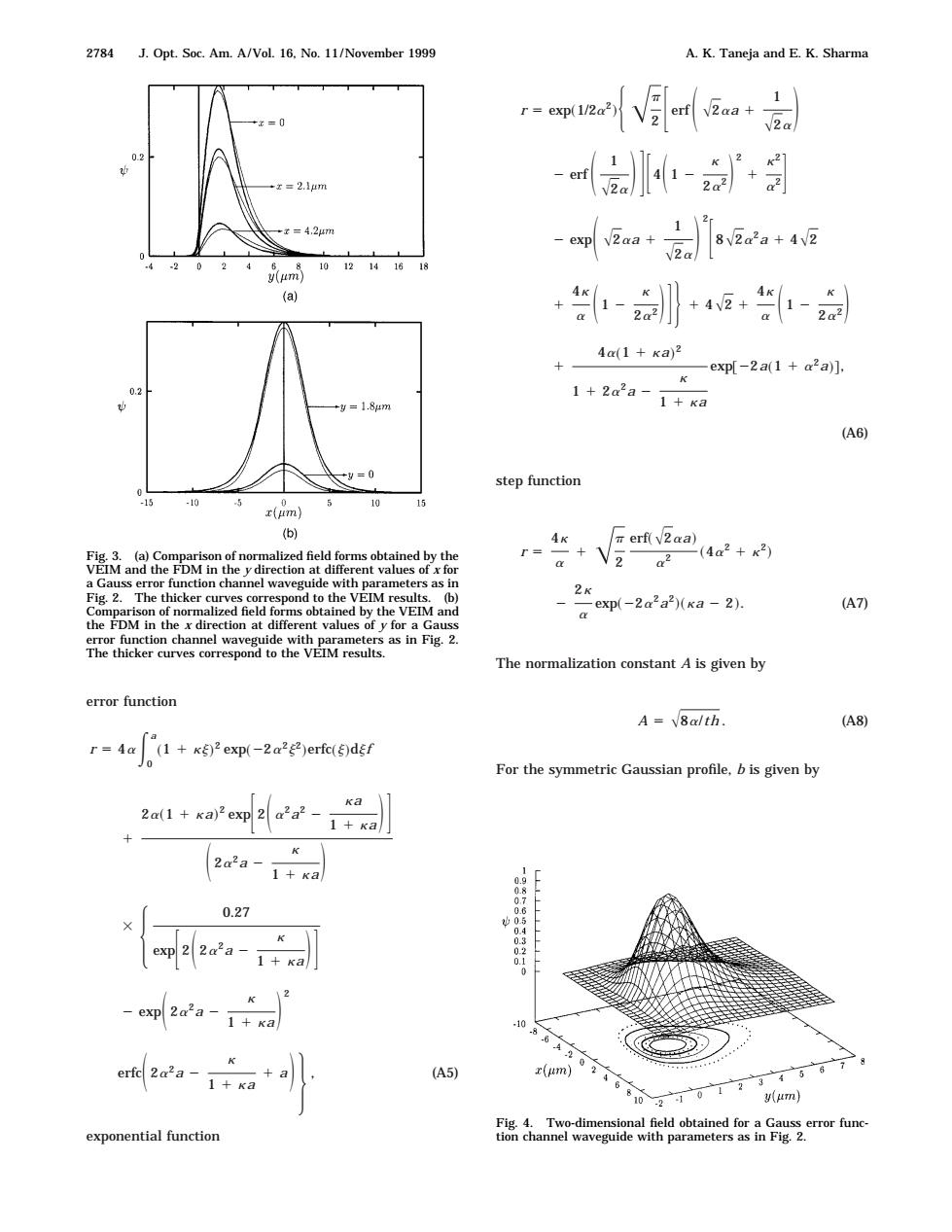
2784 J.Opt.Soc.Am.A/Vol.16,No.11/November 1999 A.K.Taneja and E.K.Sharma r=owaV目daa+ 0.2 x=2.1m m-剑 -x=4,27n 82a2a+42 -20 8101214.1618 y(um) (a) +-+4+- 4a(1+Ka)2 X exp[-2a(1+a2a)], K 02 +y=1.84m 1+2a2a-1+ka (A6) *9=0 step function 0 15 10 0 10 15 r(um) (b) 4K πerf(V2aa) Fig.3.(a)Comparison of normalized field forms obtained by the r=+V2 a2 (4a2+x3) VEIM and the FDM in the y direction at different values of x for a Gauss error function channel waveguide with parameters as in Fig.2.The thicker curves correspond to the VEIM results.(b) 2K -exp(-2a2a2)(Ka-2). A7) Comparison of normalized field forms obtained by the VEIM and the FDM in the x direction at different values of y for a Gauss error function channel waveguide with parameters as in Fig.2. The thicker curves correspond to the VEIM results. The normalization constant A is given by error function A =8a/th (A8) r=4a (1 +K)2 exp(-2a2g2)erfc()dgf 0 For the symmetric Gaussian profile,b is given by Ka 2a(1 ka)2 exp 2 a2a2- 1+ka 2a2a- 1+ka 0.27 exp 22a2a 1+ka 0 exp 2a'a-1+xa 1086 erfe 2a2a c(um) 1+ka (A5) 0。 (m】 Fig.4.Two-dimensional field obtained for a Gauss error func- exponential function tion channel waveguide with parameters as in Fig.2.error function r 5 4a E 0 a ~1 1 kj! 2 exp~22a2j2!erfc~j!djf 1 2a~1 1 ka! 2 expF 2S a2a2 2 ka 1 1 kaDG S 2a2a 2 k 1 1 kaD 3 H 0.27 expF 2S 2a2a 2 k 1 1 kaDG 2 expS 2a2a 2 k 1 1 kaD 2 erfcS 2a2a 2 k 1 1 ka 1 aD J , (A5) exponential function r 5 exp~1/2a2!HAp 2 F erf S A2aa 1 1 A2a D 2 erf S 1 A2a DGF 4S 1 2 k 2a2 D 2 1 k2 a2G 2 expS A2aa 1 1 A2a D 2 F 8A2a2a 1 4A2 1 4k a S 1 2 k 2a2 DGJ 1 4A2 1 4k a S 1 2 k 2a2 D 1 4a~1 1 ka! 2 1 1 2a2a 2 k 1 1 ka exp@22a~1 1 a2a!#, (A6) step function r 5 4k a 1 Ap 2 erf~A2aa! a2 ~4a2 1 k2! 2 2k a exp~22a2a2!~ka 2 2!. (A7) The normalization constant A is given by A 5 A8a/th . (A8) For the symmetric Gaussian profile, b is given by Fig. 3. (a) Comparison of normalized field forms obtained by the VEIM and the FDM in the y direction at different values of x for a Gauss error function channel waveguide with parameters as in Fig. 2. The thicker curves correspond to the VEIM results. (b) Comparison of normalized field forms obtained by the VEIM and the FDM in the x direction at different values of y for a Gauss error function channel waveguide with parameters as in Fig. 2. The thicker curves correspond to the VEIM results. Fig. 4. Two-dimensional field obtained for a Gauss error function channel waveguide with parameters as in Fig. 2. 2784 J. Opt. Soc. Am. A/Vol. 16, No. 11/November 1999 A. K. Taneja and E. K. Sharma