正在加载图片...
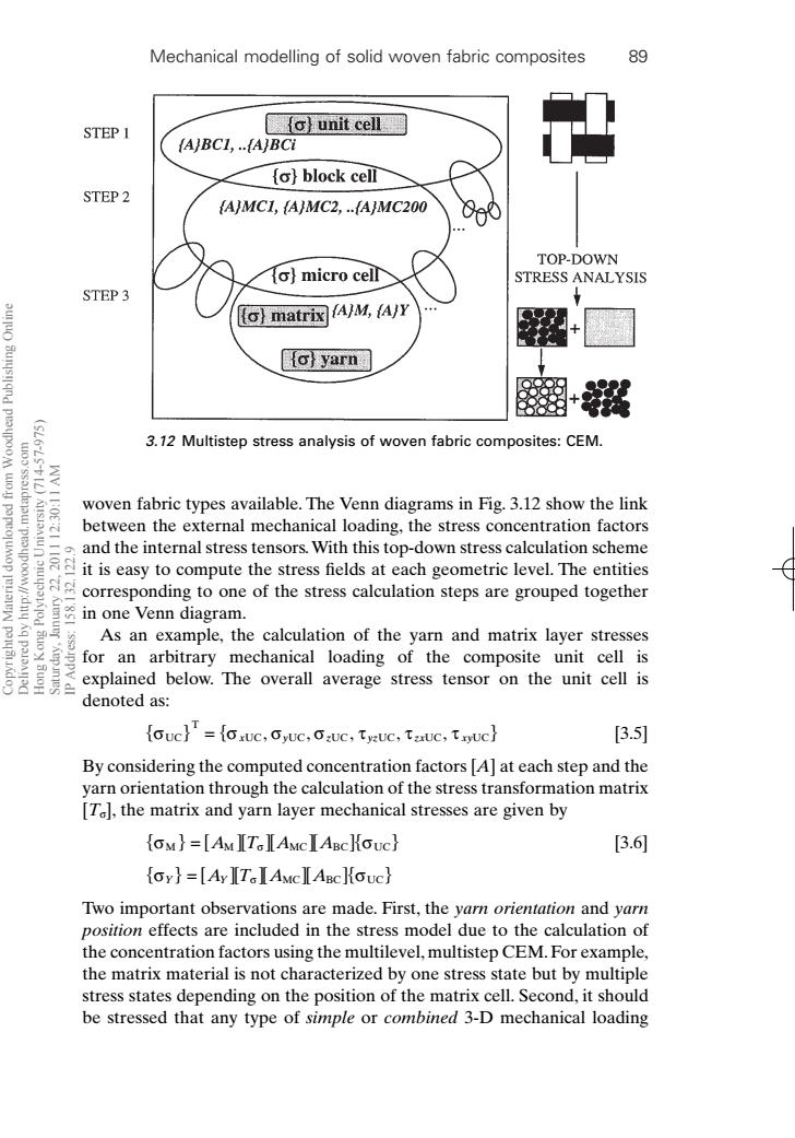
Mechanical modelling of solid woven fabric composites 89 STEP 1 o)unit cell fA/BCL,…ABCI o}block cell STEP 2 {AMC1,AMC2,…fAMC200 TOP-DOWN fo)micro celr STRESS ANALYSIS STEP 3 o)matrix☒AM,Ayy o)yarn 3.12 Multistep stress analysis of woven fabric composites:CEM. WV IL:OE woven fabric types available.The Venn diagrams in Fig.3.12 show the link between the external mechanical loading,the stress concentration factors iseasy to compute the stress fields at each geometric level.The e and the internal stress tensors.With this top-down stress calculation scheme corresponding to one of the stress calculation steps are grouped together in one Venn diagram. As an example,the calculation of the yarn and matrix layer stresses for an arbitrary mechanical loading of the composite unit cell is explained below.The overall average stress tensor on the unit cell is denoted as: ouc}'=oxuc,Gyuc,Guc,tsuc,tauc,txuc} [3.5] By considering the computed concentration factors [A]at each step and the yarn orientation through the calculation of the stress transformation matrix [T],the matrix and yarn layer mechanical stresses are given by oM}=[AMITIAMcIABcHGuc} [3.6 oy}=[AyIT IAMclABcHOuc} Two important observations are made.First,the yarn orientation and yarn position effects are included in the stress model due to the calculation of the concentration factors using the multilevel,multistep CEM.For example, the matrix material is not characterized by one stress state but by multiple stress states depending on the position of the matrix cell.Second,it should be stressed that any type of simple or combined 3-D mechanical loadingwoven fabric types available. The Venn diagrams in Fig. 3.12 show the link between the external mechanical loading, the stress concentration factors and the internal stress tensors.With this top-down stress calculation scheme it is easy to compute the stress fields at each geometric level. The entities corresponding to one of the stress calculation steps are grouped together in one Venn diagram. As an example, the calculation of the yarn and matrix layer stresses for an arbitrary mechanical loading of the composite unit cell is explained below. The overall average stress tensor on the unit cell is denoted as: [3.5] By considering the computed concentration factors [A] at each step and the yarn orientation through the calculation of the stress transformation matrix [Ts], the matrix and yarn layer mechanical stresses are given by [3.6] Two important observations are made. First, the yarn orientation and yarn position effects are included in the stress model due to the calculation of the concentration factors using the multilevel, multistep CEM. For example, the matrix material is not characterized by one stress state but by multiple stress states depending on the position of the matrix cell. Second, it should be stressed that any type of simple or combined 3-D mechanical loading { } s s Y Y = [ ][ ][ ][ ] AT A A s MC BC UC { } { } s s M M MC BC UC = [ ][ ][ ][ ] ATA A s { } s ssst t t UC T { } = { } x y z yz zx xy UC UC UC UC UC UC ,,, , , Mechanical modelling of solid woven fabric composites 89 3.12 Multistep stress analysis of woven fabric composites: CEM. RIC3 7/10/99 7:37 PM Page 89 Copyrighted Material downloaded from Woodhead Publishing Online Delivered by http://woodhead.metapress.com Hong Kong Polytechnic University (714-57-975) Saturday, January 22, 2011 12:30:11 AM IP Address: 158.132.122.9