正在加载图片...
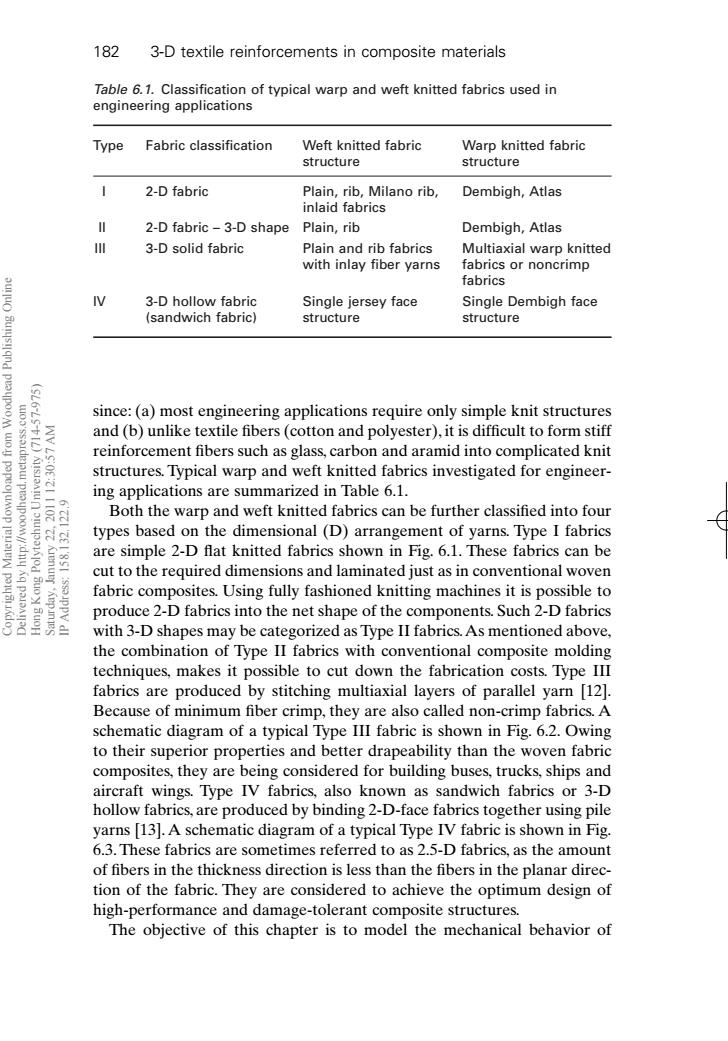
182 3-D textile reinforcements in composite materials Table 6.1.Classification of typical warp and weft knitted fabrics used in engineering applications Type Fabric classification Weft knitted fabric Warp knitted fabric structure structure 2-D fabric Plain,rib,Milano rib, Dembigh,Atlas inlaid fabrics 2-D fabric-3-D shape Plain,rib Dembigh,Atlas 川 3-D solid fabric Plain and rib fabrics Multiaxial warp knitted with inlay fiber yarns fabrics or noncrimp fabrics 3-D hollow fabric Single jersey face Single Dembigh face (sandwich fabric) structure structure since:(a)most engineering applications require only simple knit structures WV LS:OE and (b)unlike textile fibers (cotton and polyester),it is difficult to form stiff reinforcement fibers such as glass,carbon and aramid into complicated knit structures.Typical warp and weft knitted fabrics investigated for engineer- 2110 ing applications are summarized in Table 6.1. Both the warp and weft knitted fabrics can be further classified into four types based on the dimensional(D)arrangement of yarns.Type I fabrics are simple 2-D flat knitted fabrics shown in Fig.6.1.These fabrics can be cut to the required dimensions and laminated just as in conventional woven 豆 fabric composites.Using fully fashioned knitting machines it is possible to produce 2-D fabrics into the net shape of the components.Such 2-D fabrics with 3-D shapes may be categorized as Type II fabrics.As mentioned above, the combination of Type II fabrics with conventional composite molding techniques,makes it possible to cut down the fabrication costs.Type III fabrics are produced by stitching multiaxial layers of parallel yarn [12]. Because of minimum fiber crimp,they are also called non-crimp fabrics.A schematic diagram of a typical Type III fabric is shown in Fig.6.2.Owing to their superior properties and better drapeability than the woven fabric composites,they are being considered for building buses,trucks,ships and aircraft wings.Type IV fabrics,also known as sandwich fabrics or 3-D hollow fabrics,are produced by binding 2-D-face fabrics together using pile yarns [13].A schematic diagram of a typical Type IV fabric is shown in Fig. 6.3.These fabrics are sometimes referred to as 2.5-D fabrics,as the amount of fibers in the thickness direction is less than the fibers in the planar direc- tion of the fabric.They are considered to achieve the optimum design of high-performance and damage-tolerant composite structures. The objective of this chapter is to model the mechanical behavior ofsince: (a) most engineering applications require only simple knit structures and (b) unlike textile fibers (cotton and polyester), it is difficult to form stiff reinforcement fibers such as glass, carbon and aramid into complicated knit structures. Typical warp and weft knitted fabrics investigated for engineering applications are summarized in Table 6.1. Both the warp and weft knitted fabrics can be further classified into four types based on the dimensional (D) arrangement of yarns. Type I fabrics are simple 2-D flat knitted fabrics shown in Fig. 6.1. These fabrics can be cut to the required dimensions and laminated just as in conventional woven fabric composites. Using fully fashioned knitting machines it is possible to produce 2-D fabrics into the net shape of the components. Such 2-D fabrics with 3-D shapes may be categorized as Type II fabrics.As mentioned above, the combination of Type II fabrics with conventional composite molding techniques, makes it possible to cut down the fabrication costs. Type III fabrics are produced by stitching multiaxial layers of parallel yarn [12]. Because of minimum fiber crimp, they are also called non-crimp fabrics. A schematic diagram of a typical Type III fabric is shown in Fig. 6.2. Owing to their superior properties and better drapeability than the woven fabric composites, they are being considered for building buses, trucks, ships and aircraft wings. Type IV fabrics, also known as sandwich fabrics or 3-D hollow fabrics, are produced by binding 2-D-face fabrics together using pile yarns [13]. A schematic diagram of a typical Type IV fabric is shown in Fig. 6.3. These fabrics are sometimes referred to as 2.5-D fabrics, as the amount of fibers in the thickness direction is less than the fibers in the planar direction of the fabric. They are considered to achieve the optimum design of high-performance and damage-tolerant composite structures. The objective of this chapter is to model the mechanical behavior of 182 3-D textile reinforcements in composite materials Table 6.1. Classification of typical warp and weft knitted fabrics used in engineering applications Type Fabric classification Weft knitted fabric Warp knitted fabric structure structure I 2-D fabric Plain, rib, Milano rib, Dembigh, Atlas inlaid fabrics II 2-D fabric – 3-D shape Plain, rib Dembigh, Atlas III 3-D solid fabric Plain and rib fabrics Multiaxial warp knitted with inlay fiber yarns fabrics or noncrimp fabrics IV 3-D hollow fabric Single jersey face Single Dembigh face (sandwich fabric) structure structure RIC6 7/10/99 8:11 PM Page 182 Copyrighted Material downloaded from Woodhead Publishing Online Delivered by http://woodhead.metapress.com Hong Kong Polytechnic University (714-57-975) Saturday, January 22, 2011 12:30:57 AM IP Address: 158.132.122.9