正在加载图片...
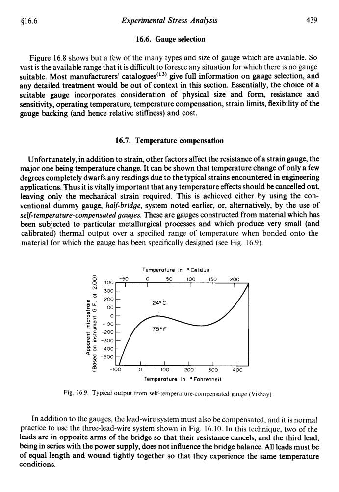
$16.6 Experimental Stress Analysis 439 16.6.Gauge selection Figure 16.8 shows but a few of the many types and size of gauge which are available.So vast is the available range that it is difficult to foresee any situation for which there is no gauge suitable.Most manufacturers'catalogues(13)give full information on gauge selection,and any detailed treatment would be out of context in this section.Essentially,the choice of a suitable gauge incorporates consideration of physical size and form,resistance and sensitivity,operating temperature,temperature compensation,strain limits,flexibility of the gauge backing (and hence relative stiffness)and cost. 16.7.Temperature compensation Unfortunately,in addition to strain,other factors affect the resistance of a strain gauge,the major one being temperature change.It can be shown that temperature change of only a few degrees completely dwarfs any readings due to the typical strains encountered in engineering applications.Thus it is vitally important that any temperature effects should be cancelled out, leaving only the mechanical strain required.This is achieved either by using the con- ventional dummy gauge,half-bridge,system noted earlier,or,alternatively,by the use of self-temperature-compensated gauges.These are gauges constructed from material which has been subjected to particular metallurgical processes and which produce very small (and calibrated)thermal output over a specified range of temperature when bonded onto the material for which the gauge has been specifically designed(see Fig.16.9). Temperature in Celsius -50 0 50100150 200 400 6 300 200 24°C IcO -100 759F -200 -300 400 -500 -100 0 100200300 400 Temperature in .Fohrenheit Fig.16.9.Typical output from self-temperature-compensated gauge (Vishay). In addition to the gauges,the lead-wire system must also be compensated.and it is normal practice to use the three-lead-wire system shown in Fig.16.10.In this technique,two of the leads are in opposite arms of the bridge so that their resistance cancels,and the third lead, being in series with the power supply,does not influence the bridge balance.All leads must be of equal length and wound tightly together so that they experience the same temperature conditions.$16.6 Experimental Stress Analysis 439 16.6. Gauge selection Figure 16.8 shows but a few of the many types and size of gauge which are available. So vast is the available range that it is difficult to foresee any situation for which there is no gauge suitable. Most manufacturers' catalogues" j) give full information on gauge selection, and any detailed treatment would be out of context in this section. Essentially, the choice of a suitable gauge incorporates consideration of physical size and form, resistance and sensitivity, operating temperature, temperature compensation, strain limits, flexibility of the gauge backing (and hence relative stiffness) and cost. 16.7. Temperature compensation Unfortunately, in addition to strain, other factors affect the resistance of a strain gauge, the major one being temperature change. It can be shown that temperature change of only a few degrees completely dwarfs any readings due to the typical strains encountered in engineering applications. Thus it is vitally important that any temperature effects should be cancelled out, leaving only the mechanical strain required. This is achieved either by using the conventional dummy gauge, half-bridge, system noted earlier, or, alternatively, by the use of self-temperature-compensated gauges. These are gauges constructed from material which has been subjected to particular metallurgical processes and which produce very small (and calibrated) thermal output over a specified range of temperature when bonded onto the material for which the gauge has been specifically designed (see Fig. 16.9). Temperature in Celsius -50 0 50 I00 150 200 I I I I I I 400 300 - 200 100 - - -100 0 100 200 300 400 Temperature in OFohrenhelt Fig. 16.9. Typical output from self-temperature-compensated gauge (Vishay) In addition to the gauges, the lead-wire system must also be compensated, and it is normal practice to use the three-lead-wire system shown in Fig. 16.10. In this technique, two of the leads are in opposite arms of the bridge so that their resistance cancels, and the third lead, being in series with the power supply, does not influence the bridge balance. All leads must be of equal length and wound tightly together so that they experience the same temperature conditions