正在加载图片...
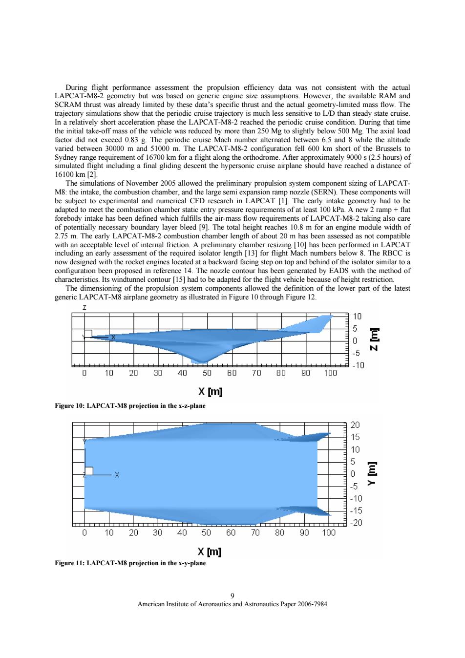
During flight performance assessment the propulsion efficiency data was not consistent with the actual LAPCAT-M8-2 geometry but was based on generic engine size assumptions.However,the available RAM and SCRAM thrust was already limited by these data's specific thrust and the actual geometry-limited mass flow.The trajectory simulations show that the periodic cruise trajectory is much less sensitive to L/D than steady state cruise. In a relatively short acceleration phase the LAPCAT-M8-2 reached the periodic cruise condition.During that time the initial take-off mass of the vehicle was reduced by more than 250 Mg to slightly below 500 Mg.The axial load factor did not exceed 0.83 g.The periodic cruise Mach number alternated between 6.5 and 8 while the altitude varied between 30000 m and 51000 m.The LAPCAT-M8-2 configuration fell 600 km short of the Brussels to Sydney range requirement of 16700 km for a flight along the orthodrome.After approximately 9000 s(2.5 hours)of simulated flight including a final gliding descent the hypersonic cruise airplane should have reached a distance of 16100km[21. The simulations of November 2005 allowed the preliminary propulsion system component sizing of LAPCAT- M8:the intake,the combustion chamber,and the large semi expansion ramp nozzle(SERN).These components will be subject to experimental and numerical CFD research in LAPCAT [1].The early intake geometry had to be adapted to meet the combustion chamber static entry pressure requirements of at least 100 kPa.A new 2 ramp+flat forebody intake has been defined which fulfills the air-mass flow requirements of LAPCAT-M8-2 taking also care of potentially necessary boundary layer bleed [9].The total height reaches 10.8 m for an engine module width of 2.75 m.The early LAPCAT-M8-2 combustion chamber length of about 20 m has been assessed as not compatible with an acceptable level of internal friction.A preliminary chamber resizing [10]has been performed in LAPCAT including an early assessment of the required isolator length [13]for flight Mach numbers below 8.The RBCC is now designed with the rocket engines located at a backward facing step on top and behind of the isolator similar to a configuration been proposed in reference 14.The nozzle contour has been generated by EADS with the method of characteristics.Its windtunnel contour [15]had to be adapted for the flight vehicle because of height restriction. The dimensioning of the propulsion system components allowed the definition of the lower part of the latest generic LAPCAT-M8 airplane geometry as illustrated in Figure 10 through Figure 12. 10 5 N -10 102030 40 5060708090 100 X [m] Figure 10:LAPCAT-M8 projection in the x-z-plane 20 =二 1 0 5 10 -20 0 1020 3040 506070 80 90 100 X [m] Figure 11:LAPCAT-M8 projection in the x-y-plane 9 American Institute of Aeronautics and Astronautics Paper 2006-7984American Institute of Aeronautics and Astronautics Paper 2006-7984 9 During flight performance assessment the propulsion efficiency data was not consistent with the actual LAPCAT-M8-2 geometry but was based on generic engine size assumptions. However, the available RAM and SCRAM thrust was already limited by these data’s specific thrust and the actual geometry-limited mass flow. The trajectory simulations show that the periodic cruise trajectory is much less sensitive to L/D than steady state cruise. In a relatively short acceleration phase the LAPCAT-M8-2 reached the periodic cruise condition. During that time the initial take-off mass of the vehicle was reduced by more than 250 Mg to slightly below 500 Mg. The axial load factor did not exceed 0.83 g. The periodic cruise Mach number alternated between 6.5 and 8 while the altitude varied between 30000 m and 51000 m. The LAPCAT-M8-2 configuration fell 600 km short of the Brussels to Sydney range requirement of 16700 km for a flight along the orthodrome. After approximately 9000 s (2.5 hours) of simulated flight including a final gliding descent the hypersonic cruise airplane should have reached a distance of 16100 km [2]. The simulations of November 2005 allowed the preliminary propulsion system component sizing of LAPCATM8: the intake, the combustion chamber, and the large semi expansion ramp nozzle (SERN). These components will be subject to experimental and numerical CFD research in LAPCAT [1]. The early intake geometry had to be adapted to meet the combustion chamber static entry pressure requirements of at least 100 kPa. A new 2 ramp + flat forebody intake has been defined which fulfills the air-mass flow requirements of LAPCAT-M8-2 taking also care of potentially necessary boundary layer bleed [9]. The total height reaches 10.8 m for an engine module width of 2.75 m. The early LAPCAT-M8-2 combustion chamber length of about 20 m has been assessed as not compatible with an acceptable level of internal friction. A preliminary chamber resizing [10] has been performed in LAPCAT including an early assessment of the required isolator length [13] for flight Mach numbers below 8. The RBCC is now designed with the rocket engines located at a backward facing step on top and behind of the isolator similar to a configuration been proposed in reference 14. The nozzle contour has been generated by EADS with the method of characteristics. Its windtunnel contour [15] had to be adapted for the flight vehicle because of height restriction. The dimensioning of the propulsion system components allowed the definition of the lower part of the latest generic LAPCAT-M8 airplane geometry as illustrated in Figure 10 through Figure 12. Figure 10: LAPCAT-M8 projection in the x-z-plane Figure 11: LAPCAT-M8 projection in the x-y-plane