正在加载图片...

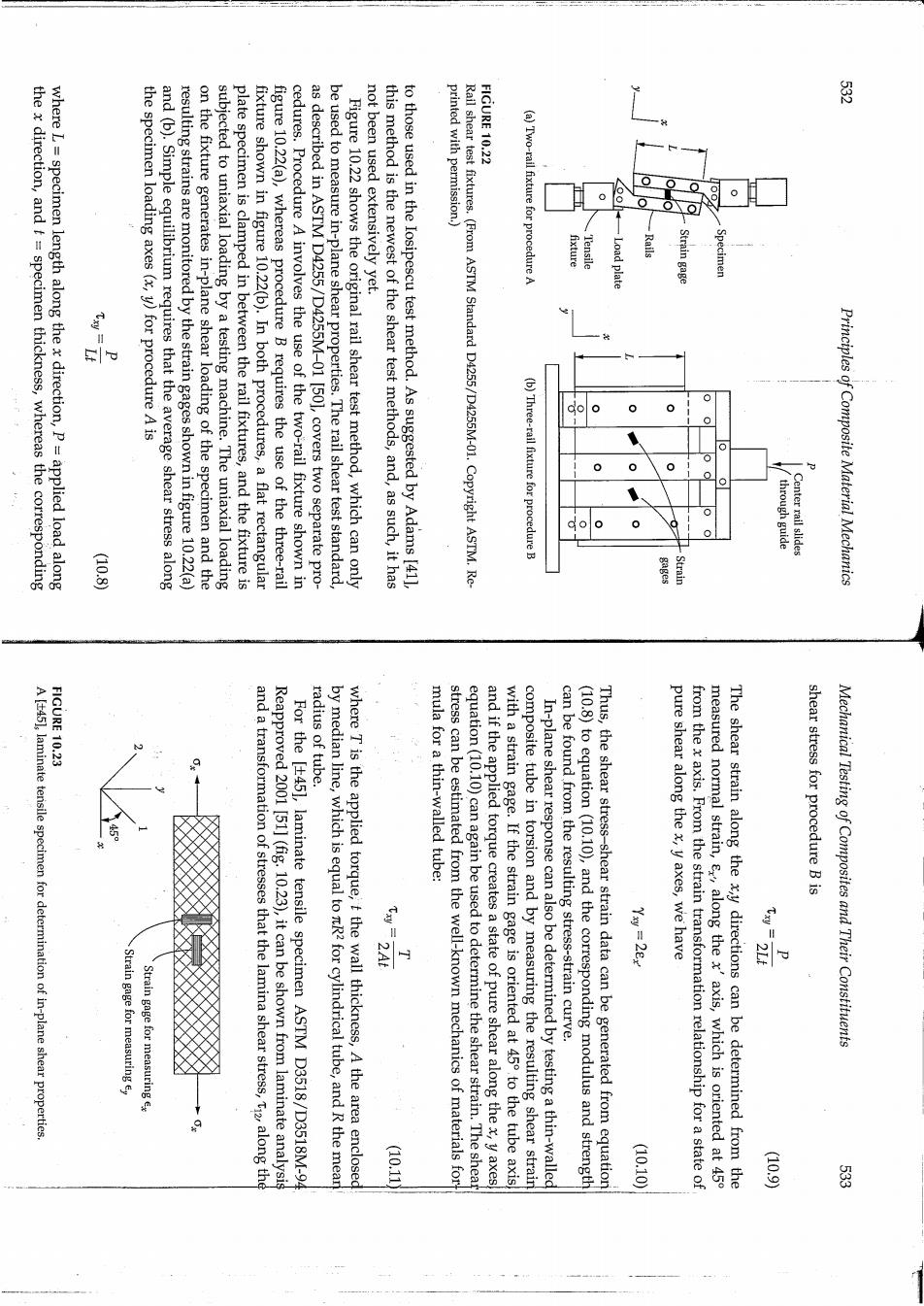
殿 the x direction,and t specimen thickness,whereas the corresponding where L specimen length along the x direction,P=applied load along the specimen loading axes(x,y)for procedure A is and (b).Simple equilibrium requires that the average shear stress along resulting strains are monitored by the strain gages shown in figure 10.22(a) on the fixture generates in-plane shear loading of the specimen and the subjected to uniaxial loading by a testing machine.The uniaxial loading plate specimen is clamped in between the rail fixtures,and the fixture is fixture shown in figure 10.22(b).In both procedures,a flat rectangular figure 10.22(a),whereas procedure B requires the use of the three-rail cedures.Procedure A involves the use of the two-rail fixture shown in as described in ASTM D4255/D4255M-01 [50],covers two separate pro- be used to measure in-plane shear properties.The rail shear test standard, Figure 10.22 shows the original rail shear test method,which can only not been used extensively yet. this method is the newest of the shear test methods,and,as such,it has to those used in the Iosipescu test method.As suggested by Adams [41], printed with permission.) FIGURE 10.22 Rail shear test fixtures.(From ASTM Standard D4255/D4255M-01.Copyright ASTM.Re- (a)Two-rail fixture for ocedure A Strain gage (b)Three-rail fixture for procedure B through guide Center rail slides Principles of Composite Material Mechanics (10.8 Strain FIGURE 10.23 radius of tube. A [t45],laminate terisile specimen for determination of in-plane shear properties mula for a thin-walled tube: can be found from the resulting stress-strain curve. pure shear along the x,y axes,we have shear stress for procedure B is Yxy =28x 101215 Mechanical Testing of Composites and Their Constituents Strain gage for measuring ey Strain gage for measuring ex and a transformation of stresses that the lamina shear stress,Ti2,along the Reapproved 2001 [51](fig.10.23),it can be shown from laminate analysis For the [45],laminate tensile specimen ASTM D3518/D3518M-94 by median line,which is equal to nR2 for cylindrical tube,and R the mear where T is the applied torque,t the wall thickness,A the area enclosed stress can be estimated from the well-known mechanics of materials for equation(10.10)can again be used to determine the shear strain.The shea and if the applied torque creates a state of pure shear along the x,y axes with a strain gage.If the strain gage is oriented at 45 to the tube axis composite tube in torsion and by measuring the resulting shear strain In-plane shear response can also be determined by testing a thin-walled (10.8)to equation(10.10),and the corresponding modulus and strength Thus,the shear stress-shear strain data can be generated from equation from the x axis.From the strain transformation relationship for a state of measured normal strain,ex,along the x'axis,which is oriented at 45 The shear strain along the x,y directions can be determined from the (10.11 (10.10) (10.9) 器