正在加载图片...
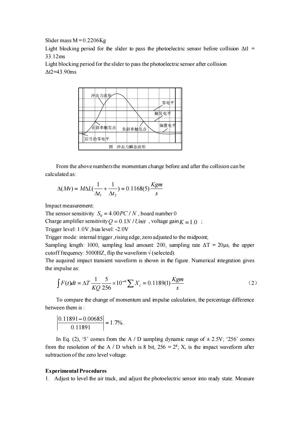
Slider mass M=0.2206Kg Light blocking period for the slider to pass the photoelectric sensor before collision Atl 33.12ms Light blocking period for the slider to pass the photoelectric sensor after collision △t2=43.90ms 冲击力波形 零电平 触拔电 斜率触发点 偏置电可 负斜率触发点 信号的零电平 图冲击力瞬态波形 From the above numbers the momentum change before and after the collision can be calculated as: 11 △(Mw)=M△L( )=0.1168(5) Kgm △11△12 Impact measurement: The sensor sensitivity So=4.00PC/N,board number 0 Charge amplifier sensitivity=0.IN /Unit voltage gainK=1.0 Trigger level:1.0V ,bias level:-2.0V Trigger mode:internal trigger,rising edge,zero adjusted to the midpoint, Sampling length:1000,sampling lead amount:200,sampling rate AT=20us,the upper cutoff frequency:5000HZ,flip the waveform(selected). The acquired impact transient waveform is shown in the figure.Numerical integration gives the impulse as: F(=AT100.119()gm (2) KQ256 To compare the change of momentum and impulse calculation,the percentage difference between them is: 0.11891-0.00685 =1.7% 0.11891 In Eq.(2),5'comes from the A/D sampling dynamic range of +2.5V;256'comes from the resolution of the A/D which is 8 bit,256 =28;X;is the impact waveform after subtraction of the zero level voltage. Experimental Procedures 1.Adjust to level the air track,and adjust the photoelectric sensor into ready state.MeasureSlider mass M = 0.2206Kg Light blocking period for the slider to pass the photoelectric sensor before collision Δt1 = 33.12ms Light blocking period for the slider to pass the photoelectric sensor after collision Δt2=43.90ms 图 冲击力瞬态波形 信号的零电平 正斜率触发点 负斜率触发点 触发电平 偏置电平 零电平 冲击力波形 From the above numbers the momentum change before and after the collision can be calculated as: s Kgm t t Mv M L ) 0.1168(5) 1 1 ( ) ( 1 2 = + = Impact measurement: The sensor sensitivity , board number 0 Charge amplifier sensitivity , voltage gain ; Trigger level: 1.0V ,bias level: -2.0V Trigger mode: internal trigger ,rising edge, zero adjusted to the midpoint; Sampling length: 1000, sampling lead amount: 200, sampling rate ΔT = 20μs, the upper cutoff frequency: 5000HZ, flip the waveform √ (selected). The acquired impact transient waveform is shown in the figure. Numerical integration gives the impulse as: s Kgm X KQ F t dt T i 10 0.1189(1) 256 1 5 ( ) 6 = = − (2) To compare the change of momentum and impulse calculation, the percentage difference between them is : 1.7% 0.11891 0.11891 0.00685 = − . In Eq. (2), ‘5’ comes from the A / D sampling dynamic range of ± 2.5V; ‘256’ comes from the resolution of the A / D which is 8 bit, 256 = 28 ; Xi is the impact waveform after subtraction of the zero level voltage. Experimental Procedures 1. Adjust to level the air track, and adjust the photoelectric sensor into ready state. Measure 0 S PC N = 4.00 / Q N Unit = 0.1 / K =1.0