正在加载图片...
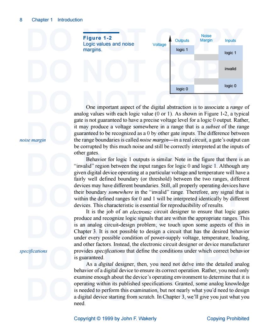
8 Chapter 1 Introduction Figure 1-2 Logic values and noise Outputs Inputs oltage margins. ogic 1 invalid logic logic One important aspect of the digital abs action is to associate a range of analog values with each logic value (0 or 1).As shown in Figure 1-2,a typical gate is not guaranteed to have a precise voltage level for a logic 0 output.Rather, it may produce a voltage somewhere in a range that is a subser of the range guaranteed to be recognized as a0 by other gate inputs.The difference between noise margin the range boundaries is called noise margin-in a real circuit,a gate's output can be corrupted by this much noise and still be correctly interpreted at the inputs of other gates Behavior for logic 1 outputs is similar.Note in the figure that there is an "invalid"region between the input ranges for logic 0 and logic 1.Although any devices may have different boundaries.Still,all properly operating devices have devices.This characteristic is essential for reproducibility of results. It is the job of an electronic circuit designer to ensure that logic gates produce and recognize logic signals that are within the appropriate ranges.This is an analog circuit-design problem;we touch upon some aspects of this in Chapter 3.It is not possible to design a circuit that has the desired behavior under every possible condition of power-supply voltage,temperature,loading. and other factors.Instead,device manufacturer specifications provides specifications that define the conditions under which correct behavior is guaranteed. Asa digital designer.then,you need not delve into the detailed analog behavior ofa digital device to ensure its correct operation.Rather,you need only examine enough about the device's operating environment to determine that it is operating within its published specifications.Granted,some analog knowledge is needed to perform this examination,but not nearly what you'd need to design a digital device starting from scratch.In Chapter 3,we'll give you just what you need. Copyright1999 by John F.Wakerly Copying Prohibited 8 Chapter 1 Introduction DO NOT COPY DO NOT COPY DO NOT COPY DO NOT COPY DO NOT COPY DO NOT COPY DO NOT COPY DO NOT COPY DO NOT COPY Copyright © 1999 by John F. Wakerly Copying Prohibited One important aspect of the digital abstraction is to associate a range of analog values with each logic value (0 or 1). As shown in Figure 1-2, a typical gate is not guaranteed to have a precise voltage level for a logic 0 output. Rather, it may produce a voltage somewhere in a range that is a subset of the range guaranteed to be recognized as a 0 by other gate inputs. The difference between the range boundaries is called noise margin—in a real circuit, a gate’s output can be corrupted by this much noise and still be correctly interpreted at the inputs of other gates. Behavior for logic 1 outputs is similar. Note in the figure that there is an “invalid” region between the input ranges for logic 0 and logic 1. Although any given digital device operating at a particular voltage and temperature will have a fairly well defined boundary (or threshold) between the two ranges, different devices may have different boundaries. Still, all properly operating devices have their boundary somewhere in the “invalid” range. Therefore, any signal that is within the defined ranges for 0 and 1 will be interpreted identically by different devices. This characteristic is essential for reproducibility of results. It is the job of an electronic circuit designer to ensure that logic gates produce and recognize logic signals that are within the appropriate ranges. This is an analog circuit-design problem; we touch upon some aspects of this in Chapter 3. It is not possible to design a circuit that has the desired behavior under every possible condition of power-supply voltage, temperature, loading, and other factors. Instead, the electronic circuit designer or device manufacturer provides specifications that define the conditions under which correct behavior is guaranteed. As a digital designer, then, you need not delve into the detailed analog behavior of a digital device to ensure its correct operation. Rather, you need only examine enough about the device’s operating environment to determine that it is operating within its published specifications. Granted, some analog knowledge is needed to perform this examination, but not nearly what you’d need to design a digital device starting from scratch. In Chapter 3, we’ll give you just what you need. logic 0 Outputs Inputs Noise Margin Voltage logic 1 logic 0 logic 1 invalid Figure 1-2 Logic values and noise margins. noise margin specifications